
How to build your own Ambilight TV with Raspberry Pi and XBMC
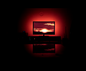
Demonstration
Hardware installation
We’ll setup the necessary hardware first.
Parts list
I’ve ordered following parts to complete the installation from boxtec.ch
| 1 x | 5V LED Pixel Strip 5m (WS2801) |
| 1 x | AC adapter 5V/10A |
| 4 x | RGB LED Strip – Pigtail Connector 20cm (pair) |
| 1 x | Heat Shrink Kit |
| 1 x | Breadboard Jumper Wire m-m (65-cable pack) |
| 1 x | 1pin dual female jumper wire (300mm) 20pcs. |
| 1 x | 5.5 x 2.1mm DC Power Jack Adapter (f) |
| 1 x | 2pin dual female jumper wire (300mm) 5pcs. |
| 2 x | Raspberry Pi Model B |
| 2 x | 8GB SD memory cards |
| 1 x | 1A MicroUSB AC adapter |
You’ll also need tools for soldering. Alternatively, you could use just one Raspberry Pi, which will act as the LED controller and the media center.
LED power consumption
Regarding the spec sheet, the 5 V LED strip consumes approx. 7.68 Watts per meter or 1.5 A. To calculate the total power consumption, we need to measure how many LEDs we can put on the TV’s back. I needed 3.8 m of the SMD LED strip for my 55 inch TV.
Power supply calculation
Total power consumption: 3.8 m LED strip x 1.5 A + 1.0 A Raspberry Pi Model B = 6.7 A / 33.5 W.
Fortunately, the Raspberry Pi requires also 5V, so you’ll be able to power up the strip and the Pi with the same 5V power supply. Just don’t forget to order a DC Power Jack Adapter for easy connectivity of the at least 7 A / 35 W – 5V power supply.
LED strip soldering
As a Software Developer, I’m not an expert in soldering but I tried to do my best. Cut the strip into 4 pieces that match your TV dimension. For easy replacing of a broken LED strip or moving the installation to another TV connect the stripes with pigtail connectors.


WS2801 LED strips have always four connectors. In my case with those pinouts:
- 5V
- GND
- SD
- CLK
Be careful, don’t twist those between the pigtails! There’s also an arrow on the strip, which marks input / output. Make sure you’re able to connect the strips from input to output with the pigtail connectors.
It’s easier to solder the connectors to the fine SMD if you put some soldering to each of the four joints in advance. Finish it up with a heat shrink, for more flexibility use non-adhesive heat shrink tubes.


LED mounting
Now, we’re coming to the fun part. It’s barely easy to mount the strips because we chose SMDs, just use the adhesive tape and you’ll be fine. It’s essential that you start mounting from the bottom right, seen from the back of the TV with the arrow on the strip pointing to the right. Later, you’ll connect from the GPIO from the RPI directly to this input of the strip. Then go ahead counter clockwise, connecting the output of the first strip to the input of the second strip and so on until you reach the bottom left. The output of the last strip is left empty, so the strips are not connected in a loop.


LED strip wiring
Wire the LED’s up as shown in the following diagram created by Philip Burgess. Please note, the diagram shown, is for the Rpi revision 1.0. This could slightly change with later revisions. Make sure the input +5V/GND connectors of the strip and the Raspberry Pi power connectors are directly connected to the DC Power Jack Adapter (DC Jack).

There’s no need for the Pi’s micro USB port anymore. I’d suggest using Breadboard Jumper wires for proper connections to the Pi’s breakout board. Leave the output connectors of the LED strip as they are.
Prototyping: All wires connected to the Raspberry Pi.

Final outcome: Raspberry Pi in black enclosure and power supply wired up.

Software installation
So, the hardware is prepared. In this section I’ll show you how to setup two different applications on the Raspberry Pi to control the LEDs. You have to chose one of them, I’d recommend Hyperion for various reasons.
Hyperion
Hyperion is newer, features a JSON interface and is easier to setup than Boblight. It is also less resource hungry. Therefore we can easily run XBMC and hyperion on the same Raspberry without performance issues.
- Install a media center distribution for the Pi. I recommend Raspbmc for beginners, it’s easier to install and less locked down.
- Boot up Raspbmc and remote login with your host computer. You’ll find the IP in XBMC under Settings -> System Info. If you’re on Windows, use putty for the ssh connection.
// Password is: raspberry
ssh pi@raspbmc-ip
Prepare hyperion installation
// Create new folder in the pi user home
mkdir hyperion && cd hyperion
// Download hyperion installation script
wget -N https://raw.githubusercontent.com/tvdzwan/hyperion/master/bin/install_hyperion.sh
// Make the install script executable
sudo chmod +x install_hyperion.sh
// Make sure boblight is not running in the background
sudo /sbin/initctl stop boblight
- Install hyperion, it will also be added to your autostart.
// Install all necessary packages for hyperion
sudo apt-get update && sudo apt-get install libqtcore4 libqtgui4 libqt4-network libusb-1.0-0 libprotobuf7 ca-certificates
// Execute the hyperion installation script
sudo sh ./install_hyperion.sh
// Hyperion should be running now, stop it again
sudo initctl stop hyperion
- Now we create the hyperion config file which includes for example the LED position informations. It’s a very readable JSON format. The configuration can initially be generated by a Java tool called “HyperCon”. Have a look at the instructions page. Download HyperCon to your Host computer where Java must be installed. If you followed the LED installation instructions above, the following settings should give you reasonable results for a start. Please adjust the LED counts and the 1st LED offset for your setup on the “Hardware” tab. We want the LED offset to line up with the LED closest to the initial input, which is connected to the Rpi GPIO. Then click “Create Hyperion Configuration” and save the json file to your Desktop. Don’t rename the file.


- Let’s copy “hyperion.config.json” to the “pi” user home directory on the Raspbmc. You can easily copy the file by using the shared folder “raspbmc”. Make sure you put it in the folder pi/hyperion. Alternatively you could use SCP for copying the file.
- Back on the Raspbmc ssh shell, copy the configuration file to the place where it will actually be picked up by hyperion at boot.
// Hyperion will by default look for the configuration at "/etc"
sudo cp hyperion.config.json /etc
// Start Hyperion
sudo initctl start hyperion
// Test if the configuration works, all LEDs should light up red for 5 seconds
hyperion-remote --priority 50 --color red --duration 5000
- We’re nearly finished. Hyperion grabs the color information directly from XBMC over an interface running on port 9090. We configured this in HyperCon, tab “External”. By default, this remote interface is disabled. In XBMC goto Settings -> Services -> Remote Control and activate both options. Reboot the system.
- We’re finished, play a movie or display some pictures and the LEDs should light up. The LED are disabled in the menu, you could easily change this setting in /etc/hyperion.config.json, look for “xbmcVideoChecker”.
- If you’d like to use the LED as mood lights simply install following excellent app and point it to the Raspberry Pi with port 19444: Hyperion for Android. For non Android users, there’s also a web app available.


Boblight
I’d recommend using ArchLinux as distribution for the Raspberry Pi, it boots in less than 10s to the command line.
- Go to http://archlinuxarm.org/platforms/armv6/raspberry-pi and follow the instructions.
- Boot up the Pi and remote login: ssh root@raspberryip password is root.
- Create a new directory and switch:
mkdir boblight && cd boblight
- We’ll install a resource optimised version of boblight for archlinux.
pacman -Sy git gcc make libx11 libxrender portaudio libxext mesa glu ffmpeg bc nano
This will install all required packages for the boblight installation.
- Let’s checkout the optimised boblight source.
git clone https://github.com/werkkrew/boblight-archarm.git
- Next commands will actually install boblight.
// Move into the cloned git repository
cd boblight-archarm
// Build and install boblight
./configure && make && make install
Now, configure ld.
// create and open a new file usr-local.conf
nano /etc/ld.so.conf.d/usr-local.conf
// in the file, type /usr/local/lib and save with ctrl + x
/usr/local/lib
// Make sure the file is closed and then execute
ldconfig
Lets configure Boblight as a deamon so it will autostart after Archlinux was booted.
// Create a new boblight service script
nano /usr/lib/systemd/system/boblight.service

// Then insert following snippet into the file and save
Description=Boblight Ambient Lighting Daemon
DefaultDependencies=no
After=network.target

[Service]
ExecStart=/usr/local/bin/boblightd
Restart=on-abort

[Install]
WantedBy=multi-user.target
Register the script as a deamon.
// Register the boblight script
systemctl enable boblight
// Start the deamon
systemctl start boblight
Boblight should now be installed and running in the background. For more details, have a look overhere: https://github.com/werkkrew/boblight-archarm#installing
- Now generate the boblight config file. Switch to the boblight checkout directory create on step 3 and make the config script executable.
chmod +x makeconfig.sh
Then execute the script
./makeconfig.sh
The script will ask you for the exact LED count mounted on each side of your TV. Use the default values for all other inputs. Wait till the script is ready, then copy everything between “——- Light section starts here ——” and “——- Light section ends here ——” into a text file on your host machine (Not on your Pi). Write down the total LED count.
- Download this preconfigured config file: SPI-WS2801-basic and open it with a texteditor on your host machine. Add your generated light section simply to the end of the file. Multiply your total LED count by 3 (RGB channels) and replace “369” with your result in the file. Then select all and copy.
- Create the actual boblight config file with
nano /etc/boblight.conf
on your Pi and paste the content of your modified config file on the host machine into it, this will take some time to complete.
- Lets test the LED config.
// Stop the deamon
systemctl stop boblight
// Manually start boblightd
boblightd
Check the output for errors.
- We’re getting closer, try firing the LEDs up. boblight-constant BB55AA All LEDs should light purple.
boblight-dispmanx installation
So, we’ve managed getting boblight to control our LEDs. Now, we’ll see how to setup another tool for sending captured screen color information right to our boblight deamon, it’s called boblight-rpi. Perform the following steps on the Raspberry Pi, that will be running the media center. A media center for example XBMC, running on this Pi will act as the video input source. Everything played on XBMC will be captured by boblight-dispmanx and sent to boblight.
- Install the newest version of OpenELEC (XBMC distribution) on your Pi: http://wiki.openelec.tv/index.php/Installing_OpenELEC_on_Raspberry_Pi#tab=Linux
- SSH to the OpenELEC Pi:
mkdir boblight-dispmanx && cd boblight-dispmanx
Checkout the source code
wget https://github.com/brooc/boblight-rpi/raw/master/src/boblight-dispmanx
Set execution permissions to the precompiled boblight-dispmanx binary.
chmod 755 boblight-dispmanx
- We have to configure the tool to actually send the captured screenshots of the TV screen to your Pi Boblight server. Create an autostart script:
nano /storage/.config/autostart.sh
Paste following sample config into the file.
#!/bin/sh
/storage/boblight-dispmanx -b on -s {archlinux-pi-ip}:19333 -o interpolation=1 -o speed=70 -o threshold=35 -o autospeed=0 -o saturation=3.0 -o value=1 -p 100 -i 0.2 -f /dev/null &
Don’t forget to replace the {placeholder} with the IP of your boblight running Pi or set it to “localhost” if you went for one Raspberry Pi. Then save the script and make it executable with
chmod +x /storage/.config/autostart.sh
- We’re done, just restart the system
sudo reboot
- Check the setup with a RGB test video. If you think the colours are to pale, try a higher value for the “-o saturation” parameter. When the lights are to slow, try setting “-o speed” to 90. If you don’t like the LED’s in the XBMC menu, just remove the “-b” parameter.
Conclusion
This is a really educational project, which will give insight into a lot of interesting technical areas reaching from compiling in the Linux shell to soldering and calculating LEDs power consumption.
For now, you’re bound to XBMC as media source for ambient light your environment. If you want to go a step further and use every HDMI input signal as media source, have a look at this how to: How to build an Ambilight for every HDMI input source
If you have any question, feel free to ask in the comments section. Enjoy your ambilight!
Hello all,
Everytime I try the hyperion Remote command i get the following error. Any ideas on how to solve error with data reading from host?
“hyperiohyperion-remote –priority 50 –color red –duration 500 0
version : V1.03.4 (brindosch-c750c41/dc6a602-1522918225
build time: Apr 5 2018 01:57:05
Connected to localhost:19444
Set color to 255 0 0
Error while reading data from host
THANKS SO MUCH FOR ANY HELP
[…] the LED’s and connect them to the connecting LED wires. They should look something like the image […]
[…] Link to example […]
Dear all,
who can help me and will update working image for raspberry pi B v2011.12 with video grabber Fushicai UTV007.
Im playing with image OpenELEC-RPi.arm-4.95.5.img.7z, but Im not able connect to file system as pi user and hyperion link is not active anymore.
Andrej
Hi. I make this twice! Whith WS2801 working. But now buy APA102 60led/m, and don’t work. Hyperion settings: led type apa102, led number is ok (all 162), cabel is ok, pinout ok…
Can you help me?
Hi Guys,
I’m having issues getting the LED’s to power. I’m using WS2801 strips I bought here: http://www.ebay.co.uk/itm/221607064973?_trksid=p2057872.m2749.l2649&var=520465031366&ssPageName=STRK%3AMEBIDX%3AIT
I appear to get one LED to light if I use an additional 5v as the LED strip has two live and ground cables. But this doesn’t seem to work with the PI as above. Any ideas what I might be doing wrong?
I have soldered the cables from the strip to female jump cables to ensure they sit firmly but no joy. otherwise there’s no connections I can see causing the issue.
I’ve also connected the strips directly to the GPiO and 5v and again one or two light up.
Put some images below:
https://unsee.cc/zitegonu/
Thanks!
Hi
Thanks for such a detailed and insightful article.
I would like to know if we can use the Led strip WS2813 (Dual signal-wire)
http://s.aliexpress.com/67zuqIra
Also, will the 60 led/m give better color spread/spectrum/depth than the 30 led/m.
Further can we do more than Ambilight… As in Ambilux.
Thanks
I have an annoying problem with my LEDs WS2801 http://www.ledlightinghut.com/ws2801ic-digital-rgb-led-strip.html . I tried using hyperion mobile app to test and i have the same result: flickering. When i completely desaturate the color and increase the intensity to max, the LEDs are white (as should be) and the flicker appears random on few LEDs.
Hi, I have a Pi2/OSMC and I’m planning to start that project. This guide looks so easy and very clear to follow. I noticed from the demonstration video that there’s a bit of delay between the screen and the back-light. It’s all understandable considering the computing power of the Pi. Is’s that delay too noticeable? Does it get annoying after a while and watching a full movie? Is there a way to improve the performance?
Thanks!
Hi you are welcome.
IMHO the delay is not really noticeable. The video was captured from the first prototype with boblight and a RPI 1. It should be even much better with hyperion.
Have fun, Christian
Every led is driven over 800Khz (ot at least in new ones is that freq) buss line, so if you have long stripe it take small delay transferring data bits next to next to next..
Will be much better if used different pin out – for example instead pushing long array data from MCU to the first led, devide the array into 8 parts and using 8 pins to control. Then you`ll get smooth and fast response. Anyway you send 24bit data per pixel. In 1M led stripe are about 60 leds. Or in other words 60x24bit = 1440bits.
Having 5m led it will need 5x60x24 = 43200bits of data per frame. Lets presume 25 frames per second , the you get 1080000bits per second. And you have only 800 kHz data bus for the leds. Other option is to make bigger distance between each led and put glass lens on top to enlarge light spreading.
Good project by the for the Author!
Thanks for the good explanation!
Does it work with a raspberry piece model c
Great article onmomo! I’m nervous about using gpio for power in the pi due to bypassing protection so I’m going to stick with micro usb. I’m no electrician so was wondering if it would be wise to connect the 5 amp psu ground to gpio even though I’m not connecting +5v?
Hi Paulo, yes I’d do so with the grounding it should reduce interferences on the spi bus.
Regards Christian
Mt LED strips came with two extra cords for 5v and ground. And when I plugged everything up the wires began smoking. What do I do. Luckily the board and LEDs still work but I had to re solder everything.
Hi Jake, that sounds terrible. The “wires” began smoking? Are you using 5v led strips / 5V power supply and not wires with a very small
cross-section?
No i bought identical to your specs. I think I wired the board on the pi wrong. What would change using the Pi model 3 B I went this route to use the built in wifi
I also just rewired with brand new strips and folloed the Hyperion tutorial to a t, but I still have no idea what I am doing wrong.
Hi,
How do you capture the TV signal? I don’t see any HDMI or other cables going from TV to RPi
Hi, please have a look here: Ambilight for ever hdmi input source this is media center only.
Cheers
Hi All!
Thanks for this tutorial!
I plan use rapsberry Pi Zero. What do you think it will work too? Or I must buy the raspberry PI 3 model B?
Thanks
You’re welcome.
It should work but it’s slightly more difficult: Pi Zero – Pinout As you can seen the there’s a SPI bus but not ready for easy access. Using a RPI3 would be easier.
Regards Chris
Hey Guys,
I use RaspPlex, do you guys know if that works also ?
Hi, Rasplex is just an hdmi source as any other so it will work just check this guide: Ambilight for hdmi
Thank you so much !
Hi,
All my leds will not light up when testing. I’ve tried connecting the pi and trying without, both ways will not work. Though connecting standardly through the supplied plug with the leds they all light up fine. Do you have any idea what I’m doing wrong
Hi,
ich stelle mich gerade etwas doof an, die Komponenten ins Deutsche zu übersetzen.
– Deine Jumper sehen dicker aus als die, die man regulär bei ebay findet.
– passende Brücken zum verbinden der LED-Strips konnte ich auch nicht finden.
Als Elektro noob hat man scheinbar die größten Probleme damit zu haben, die passenden Bezeichnungen zu finden 😉
Kannst du mir die korrekte Bezeichnung für die Kabel bzw die Stecker zum Verbinden mitteilen?
Chris
i cannot find a AC adapter 5V/10A power supply. can someone list 1?
You need to restart hyperion for changes to take effect.
Hi, thanks for this tutorial.
I am a student and I’m thinking of doing this as my project.
In my project i have to make use of a button, can i use it to switch the led strip on and off? E.g.
if (GPIO.input(17) == True): #GPIO 17 is where the button is connected
GPIO.output(26, GPIO.HIGH) #or where the led strip is connected(13 or 26)
Thank you.
Hi, you’re welcome.
You could turn off/on hyperion with a python script that reacts to the gpio status or similar.
Regards Chris
thanks for the reply
I am student too, i recently made the question of my led project, but I what I want to do is test rgb addressable led strip(http://www.ledlightmake.com/rgb-addressable-led-strip-c-80_87/)
the MCU were also unavailable for addressable led strip!!!
Thank you for this project. It is amazing. I just finished it using OSMC & RPI3. The coloring is off a bit, though. When I run: “hyperion-remote –priority 50 –color red –duration 5000”, I get the correct red. But, if I change the color to green, the leds all light up blue. If I tell it to turn them blue, they all turn green.
Do you have any idea why these colors may be reversed?
Thanks again!
Hi Walter
In hyperion.config.json, there’s a section “colorOrder” : “rgb” under “device”. Try changing it to “bgr”, perhaps it helps.
Regards
I did try that first. It didn’t seem to have any effect. Do you have to do anything once you make the change to that before it will become live?
You need to restart hyperion for changes to take effect.
I’m running “sudo service hyperion –full-restart” in between each change and I’ve changed the “colorOrder” to every combination I can think of (RGB, RBG, GRB, BRG, etc), but I see no change. Green always shows as blue and vice versa. Red seems to always remain correct.
Do I need to be restarting the Pi as well each time? I’m really at a loss here.
Did you have to do anything special on the pi3? From what I’ve read it’s mostly the same just pins 19 and 23 instead. I’ve got the LED’s and most of the wiring just waiting on the pigtails to get here.
Hi Sam, just make sure you’re using the right pins and it should be fine. Regards
[…] How to build your own Ambilight TV with Raspberry Pi and XBMC […]