How to power Logitech Circle View Homekit camera via PoE outdoors
In case you were also wondering on how one should power the IP64 rated camera outdoors with the provided indoor only rated power supply, then please continue reading. 🙂
Currently, there is no Homekit compatible camera that supports PoE for outdoor installation but one could follow this post to achieve the said. I tried to make the guide as simple as possible, no soldering skills are required.
Note, the following guide will void your Logitech Circle View warranty!
Bill of Material
Since I wanted to hide all the required components inside a EU Backbox, the dimensions of the components mattered to me. I assume a PoE source, such as PoE switch or Poe injector is already available. Next to the Logitech Circle View camera, the following components are essential.
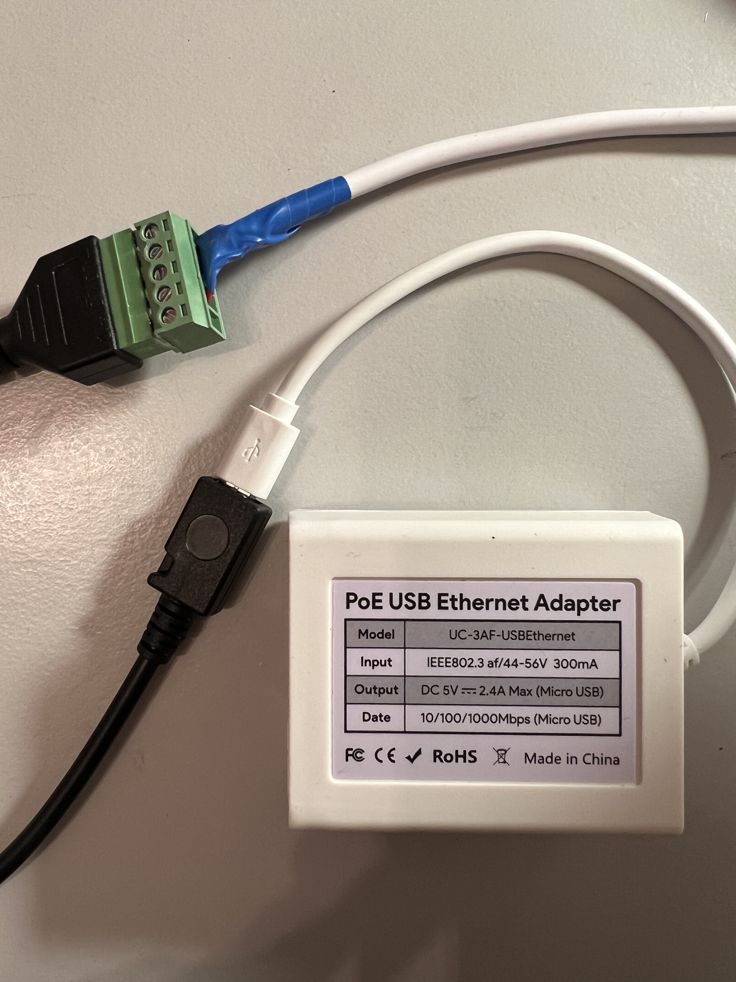
PoE Adapter to Micro USB
There are several other options available on the market. I went for UCTRONICS due to its compact dimensions and availability.
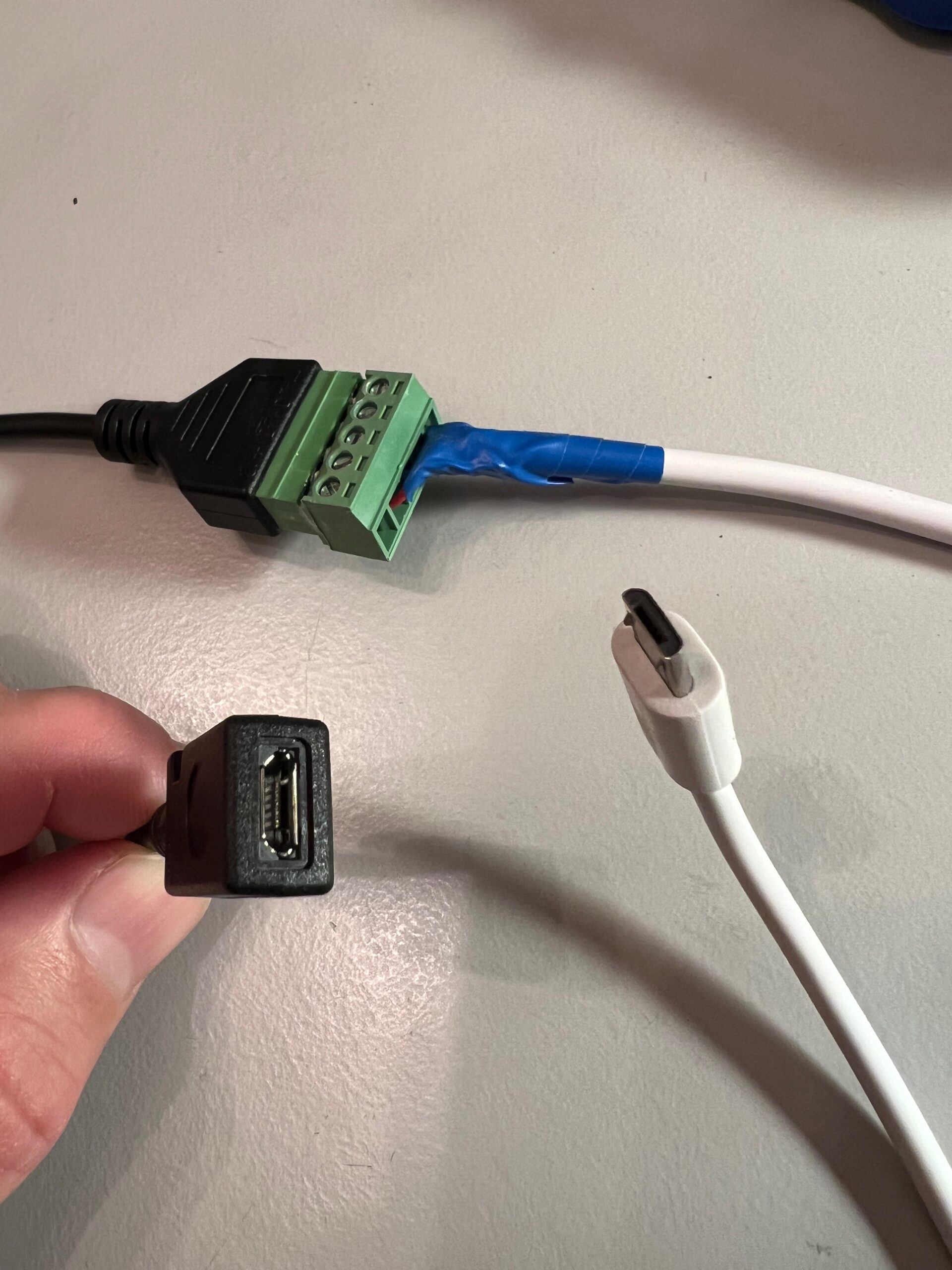
Micro USB female to screw connector
I went for this since it allowed me to detach the 5 bolt plug for easier installation but it was not really necessary. Another much more compact option would have been to choose a micro USB female connector with soldering pin outs.
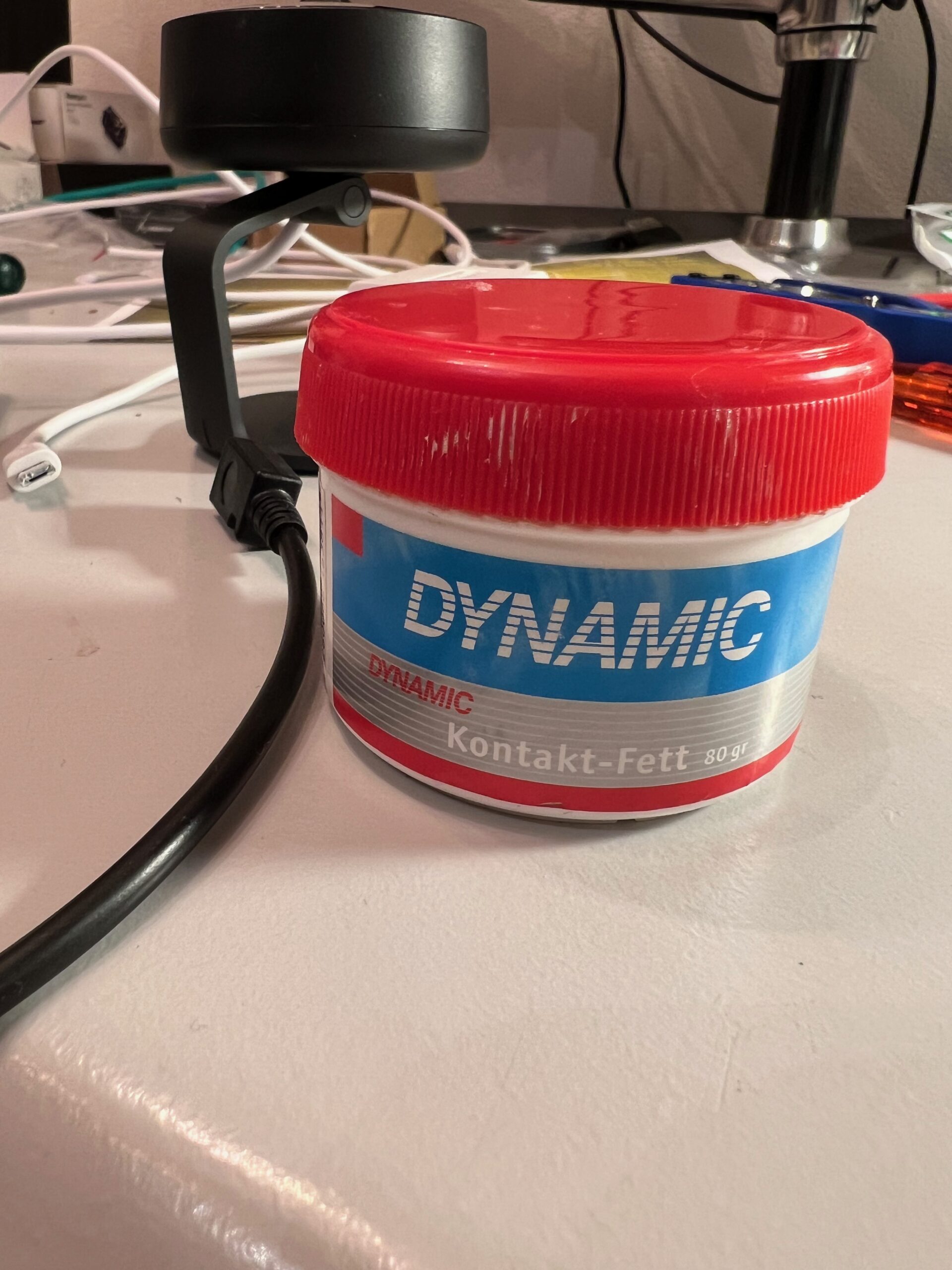
Dielectric Grease
In case the camera is going to be installed outdoors, I recommend putting a thin layer of dielectric grease on every connection to prevent corrosion. For more insights, please look at this blog.
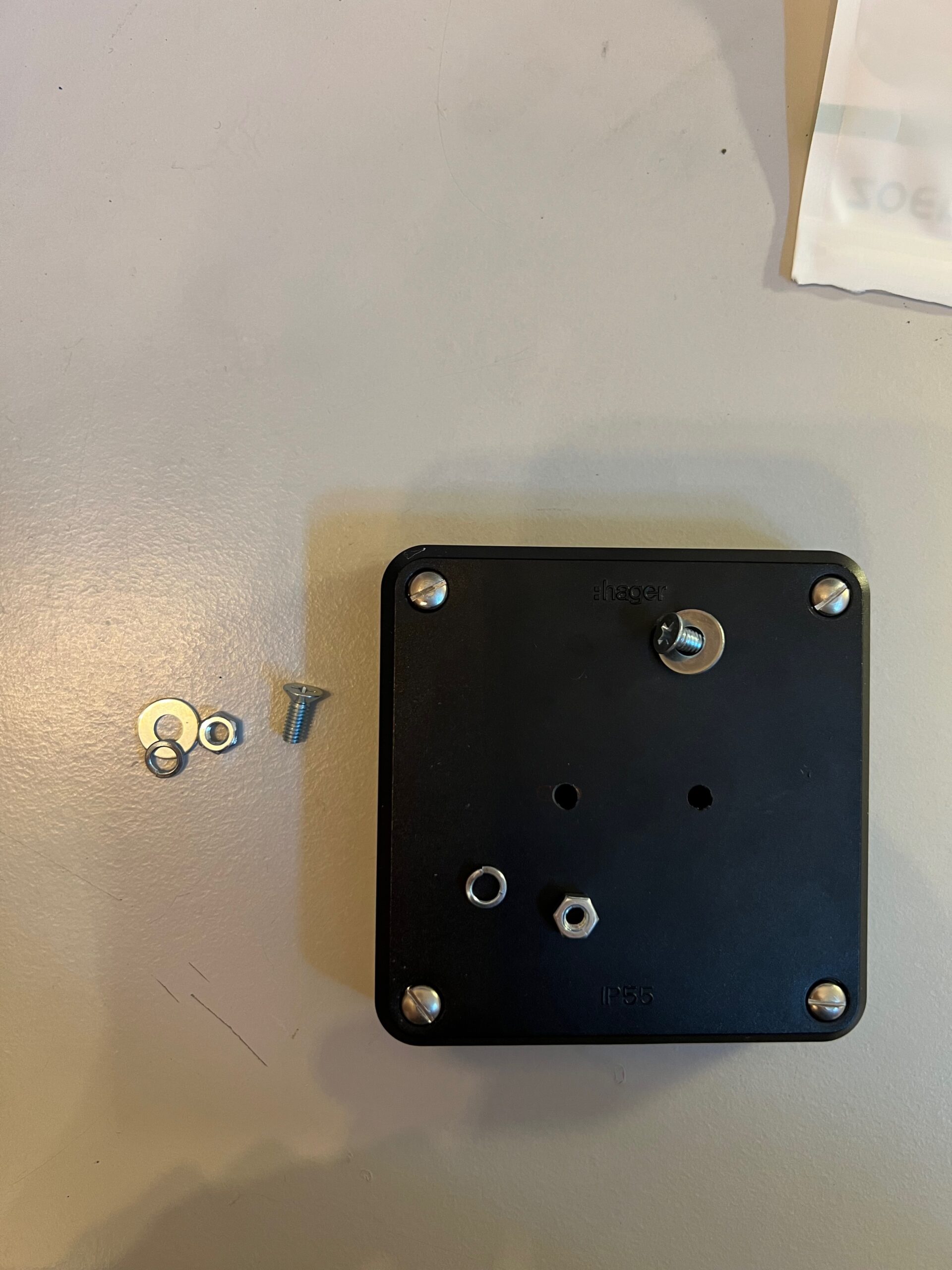
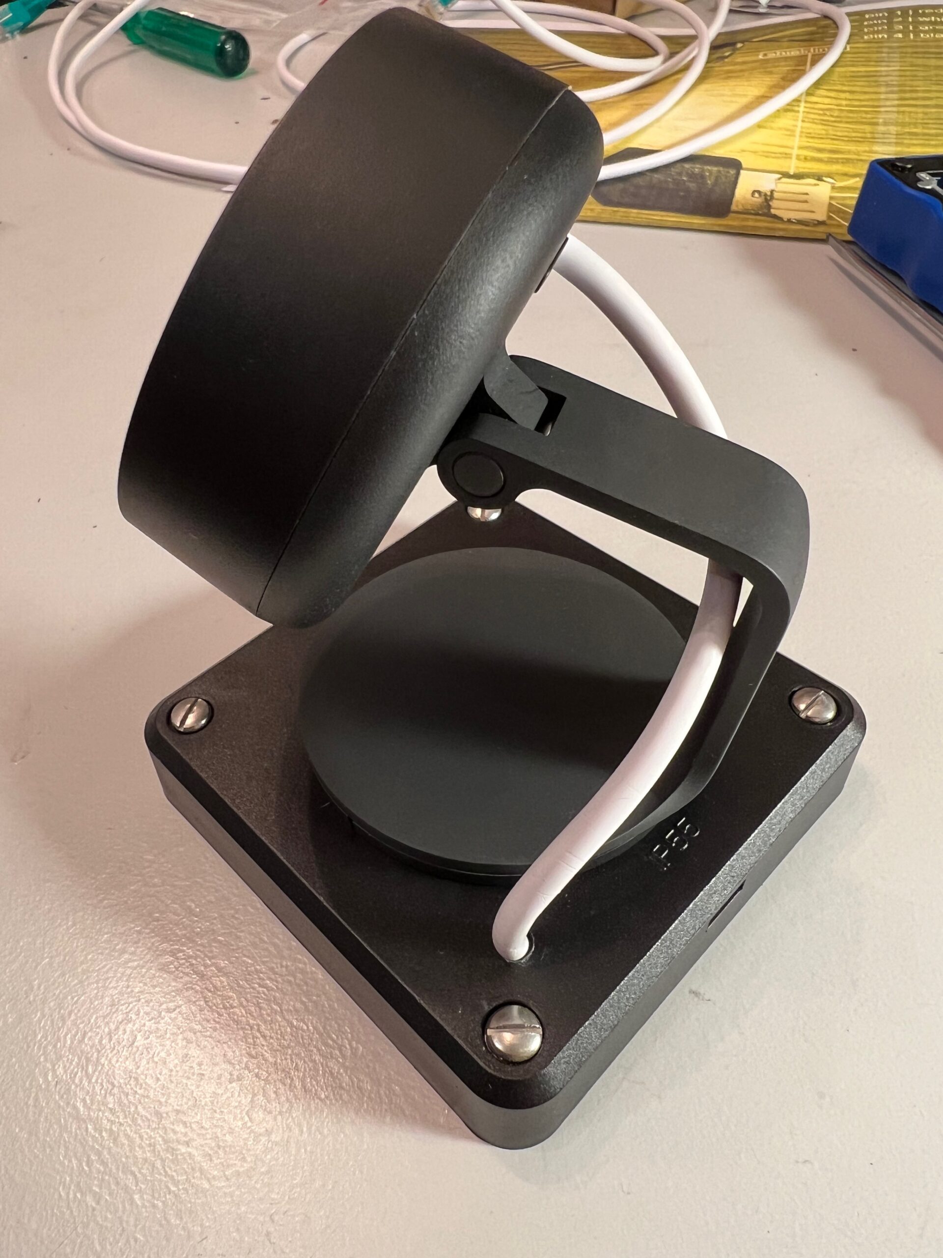
Hager Robusto outdoor blind cover (E-No 374160053)
There are also plenty of other options on the market depending on your location. I went for these because they offer plenty of space and are sturdy enough to mount the camera on it.
Connecting the dots
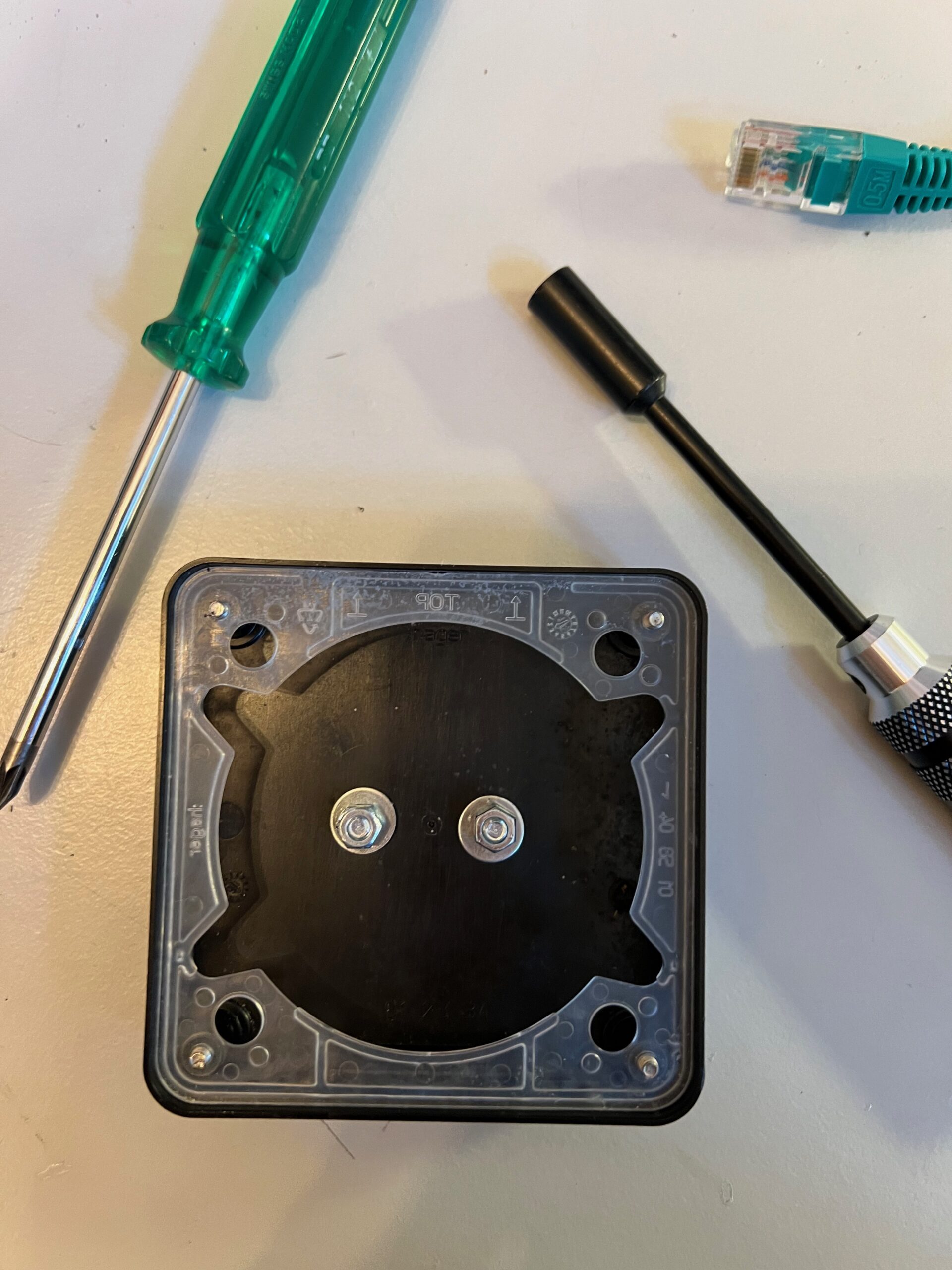
First, we need to prepare the the blind cover by drilling the two holes for the included camera mount. Then attach the mount using M4 screws. Next to the mount, we need to drill a third hole for the power cable.
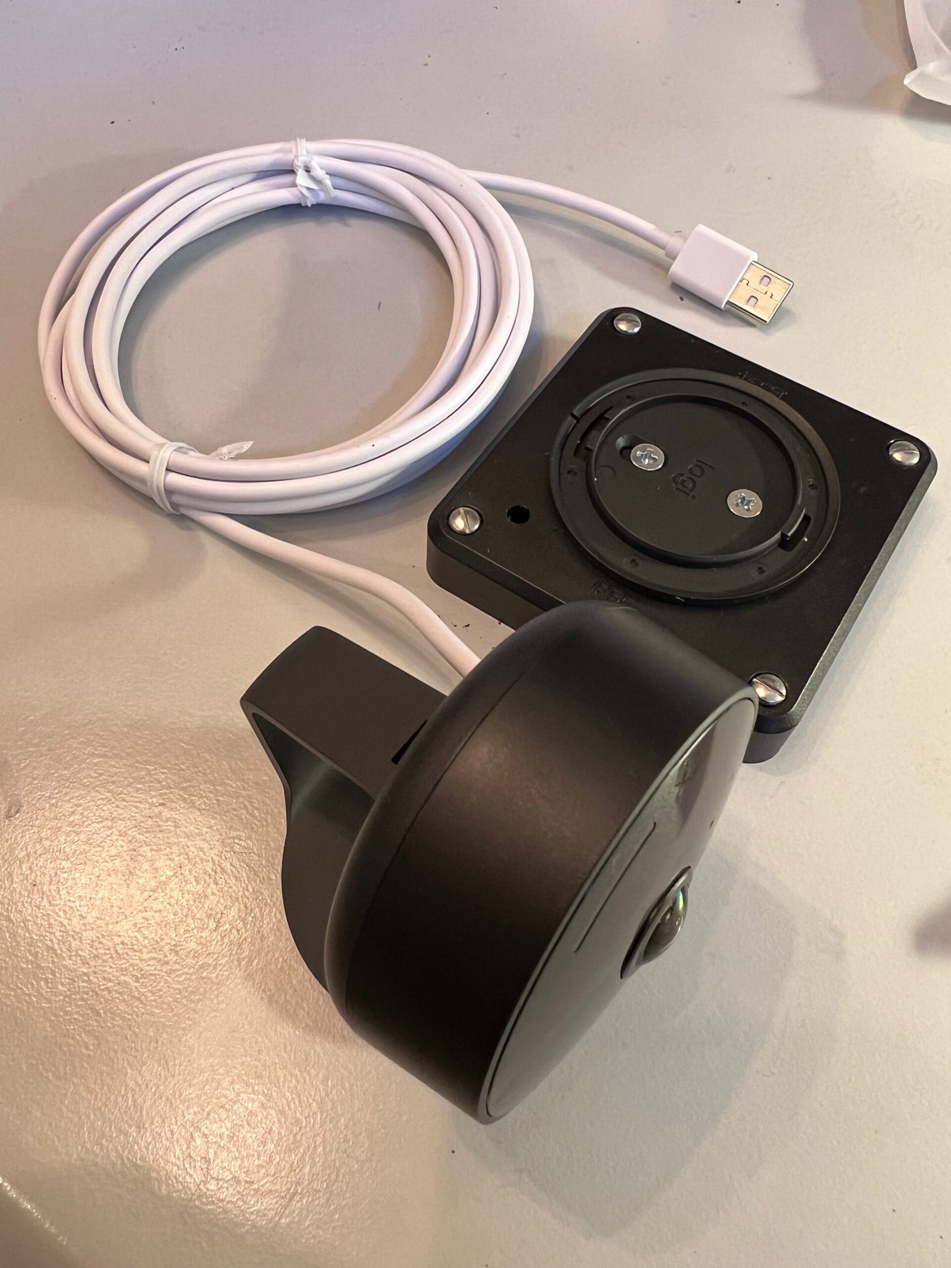
The next problem we need to solve is the much too long USB cable that is not removable without dissembling the camera case, unfortunately.
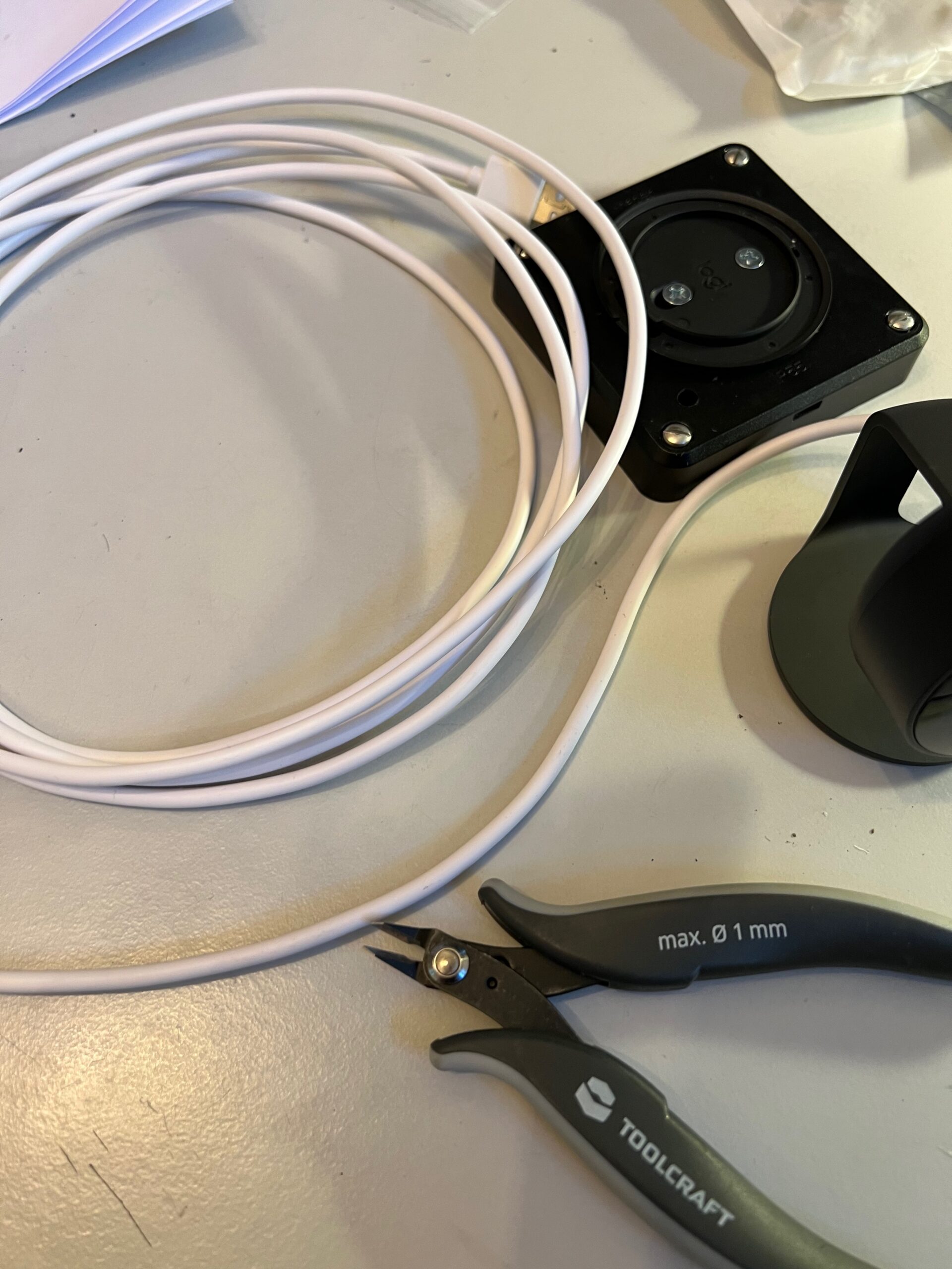
Therefore, I considered it to be less risky to cut the cable to the desired length in order to hide the installation outside. This will void your warranty!
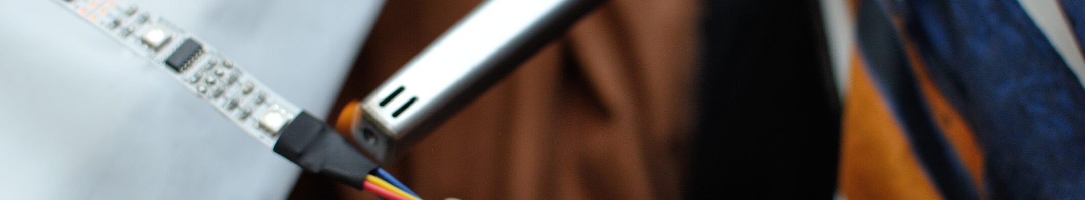
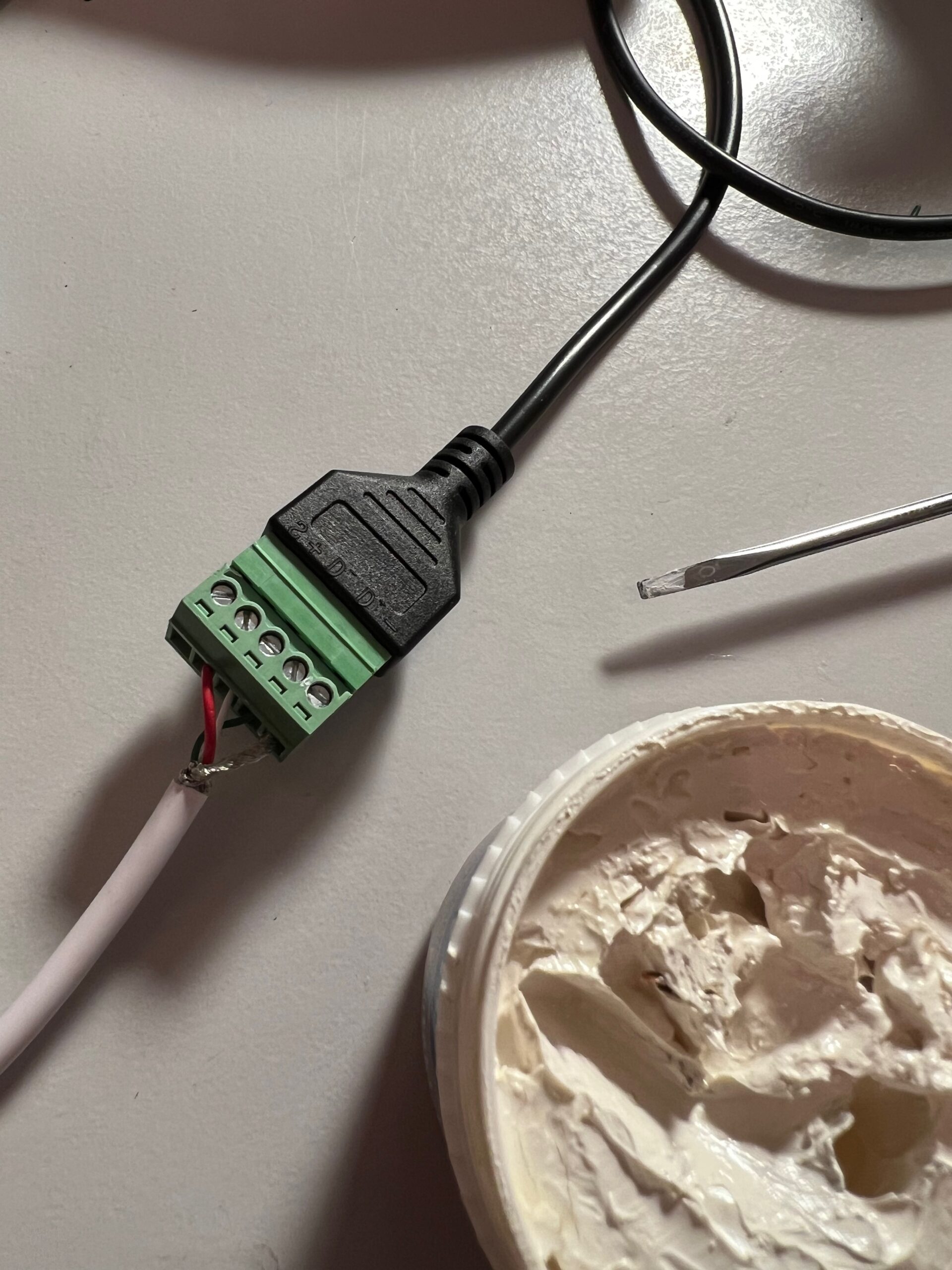
Cut the cable in to length (~30cm) and strip it very carefully. The outer shield layer should not be damaged. Then bundle and twist the shield together and also remove the additional foil on the three wires.
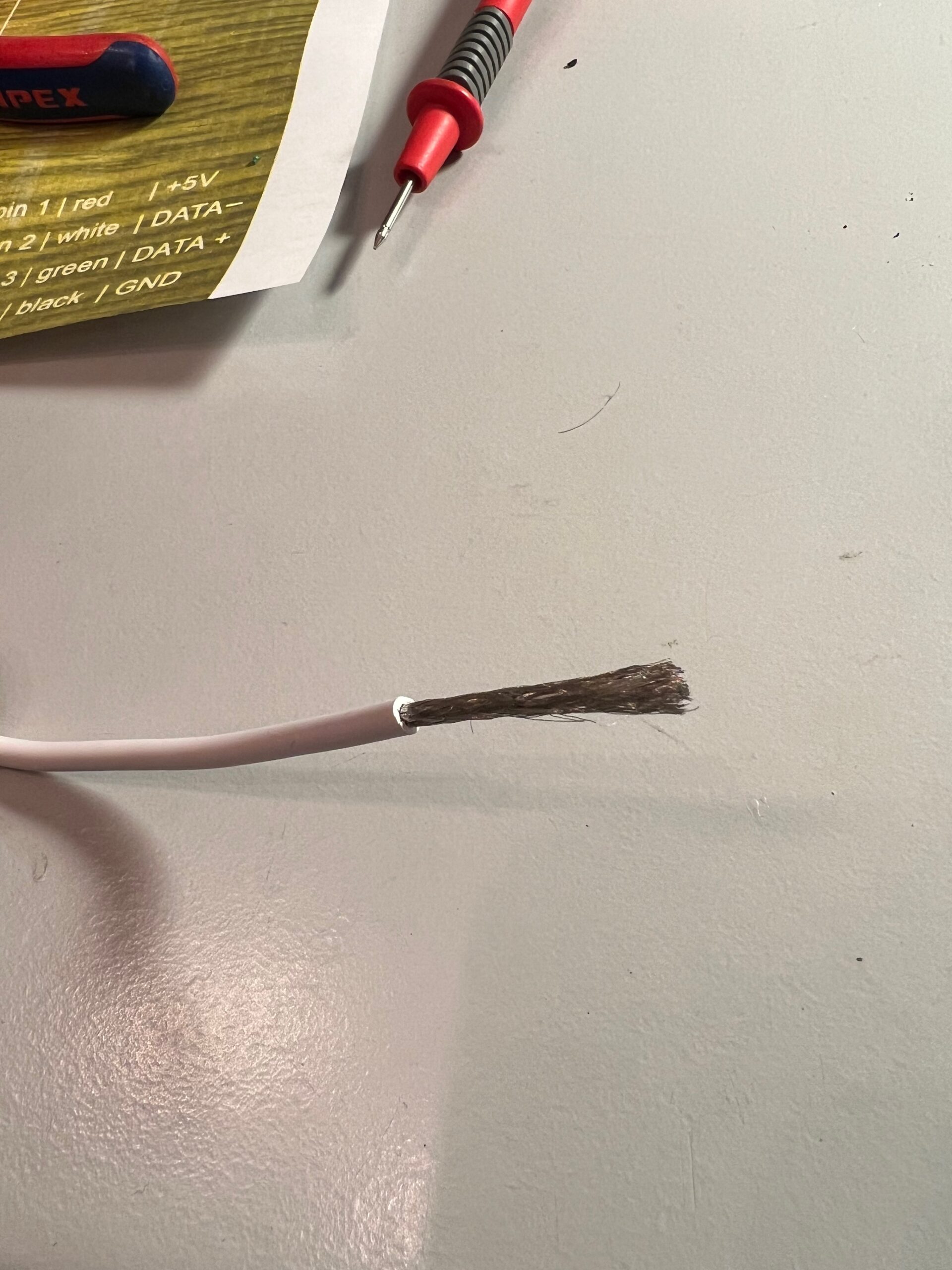
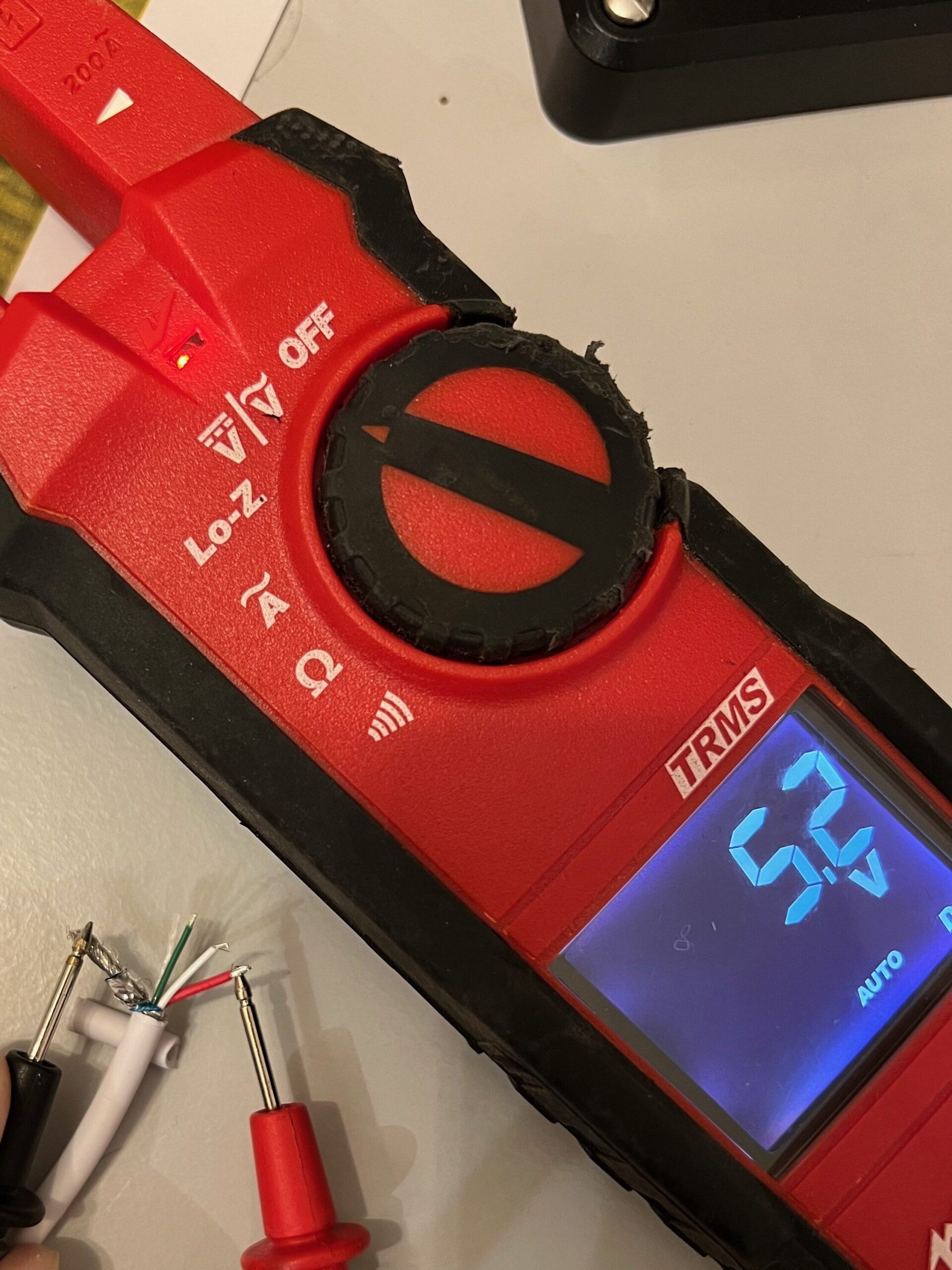
I did not expect to only find 3 coloured wires, next to the shield since the screw connector has a dedicated shield port and most USB specs suggest 4 cables. The thickest wire should be the positive (+) pole, in this case the red one and due to the lack of a 4th black wire, the shield is used as the negative (-) pole as confirmed by my voltage measurement. For the remaining two data wires, white should be data positive (+) and green data negative (-) but they are unused for this use case.
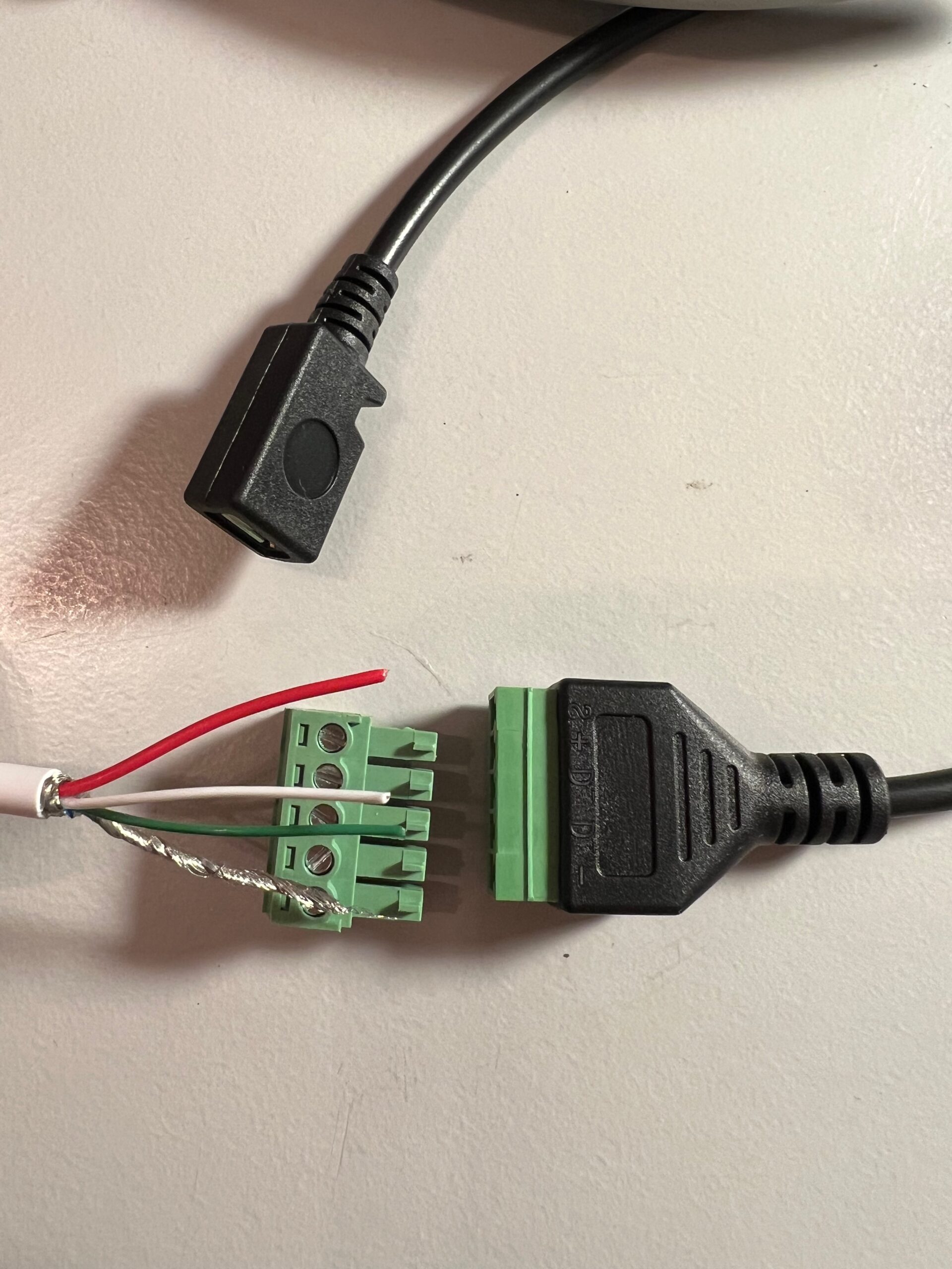
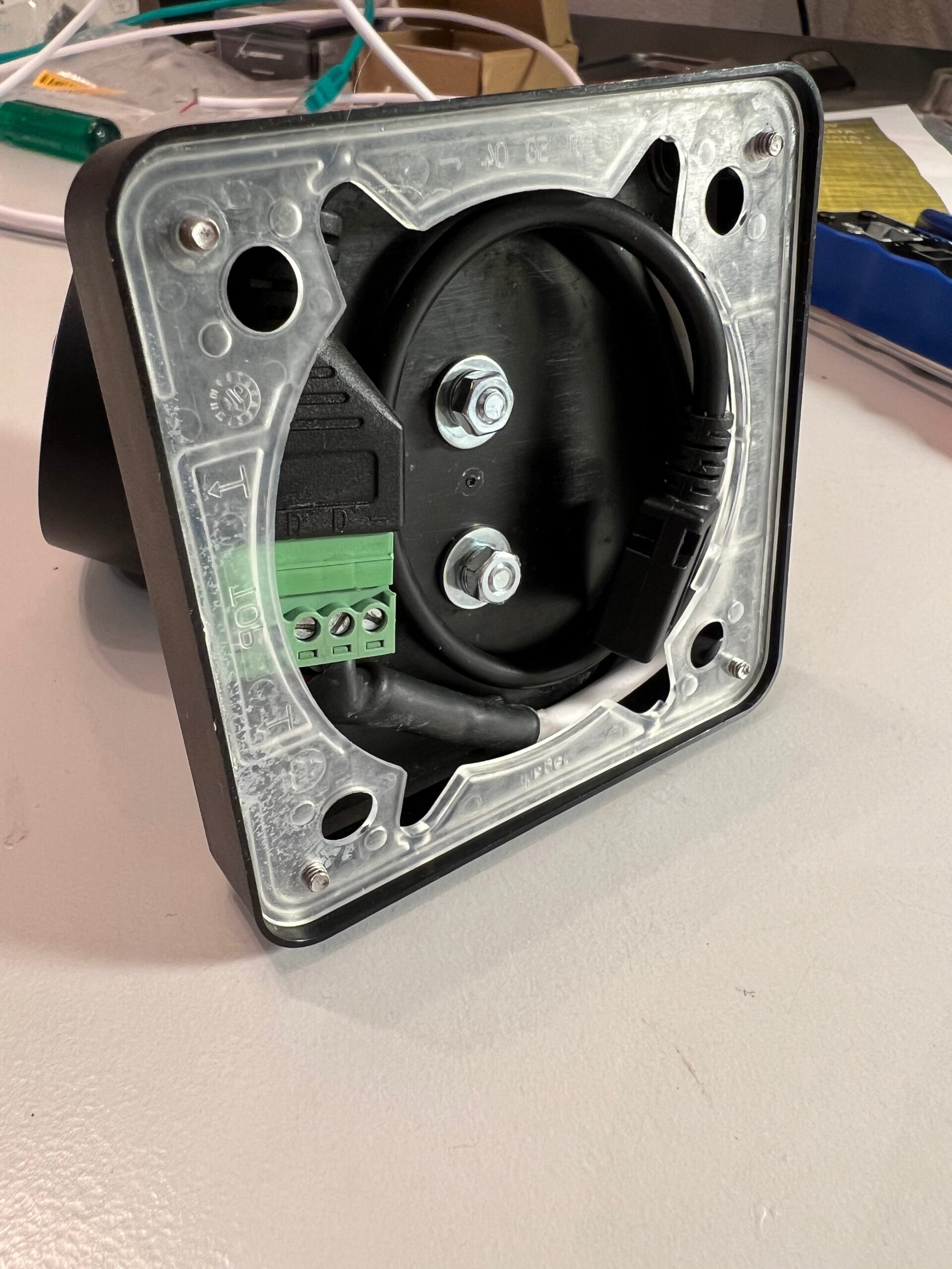
Now, we can connect the wires to the screw connector on the corresponding ports. Here the dielectric grease comes into play, add a thin layer to the connectors and wires. Remember to pull the cable first through the hole in the blind cover before attaching the screw connector. 🙂
- + = red
- – = shield
- D+ = white
- D- = green
- S = empty
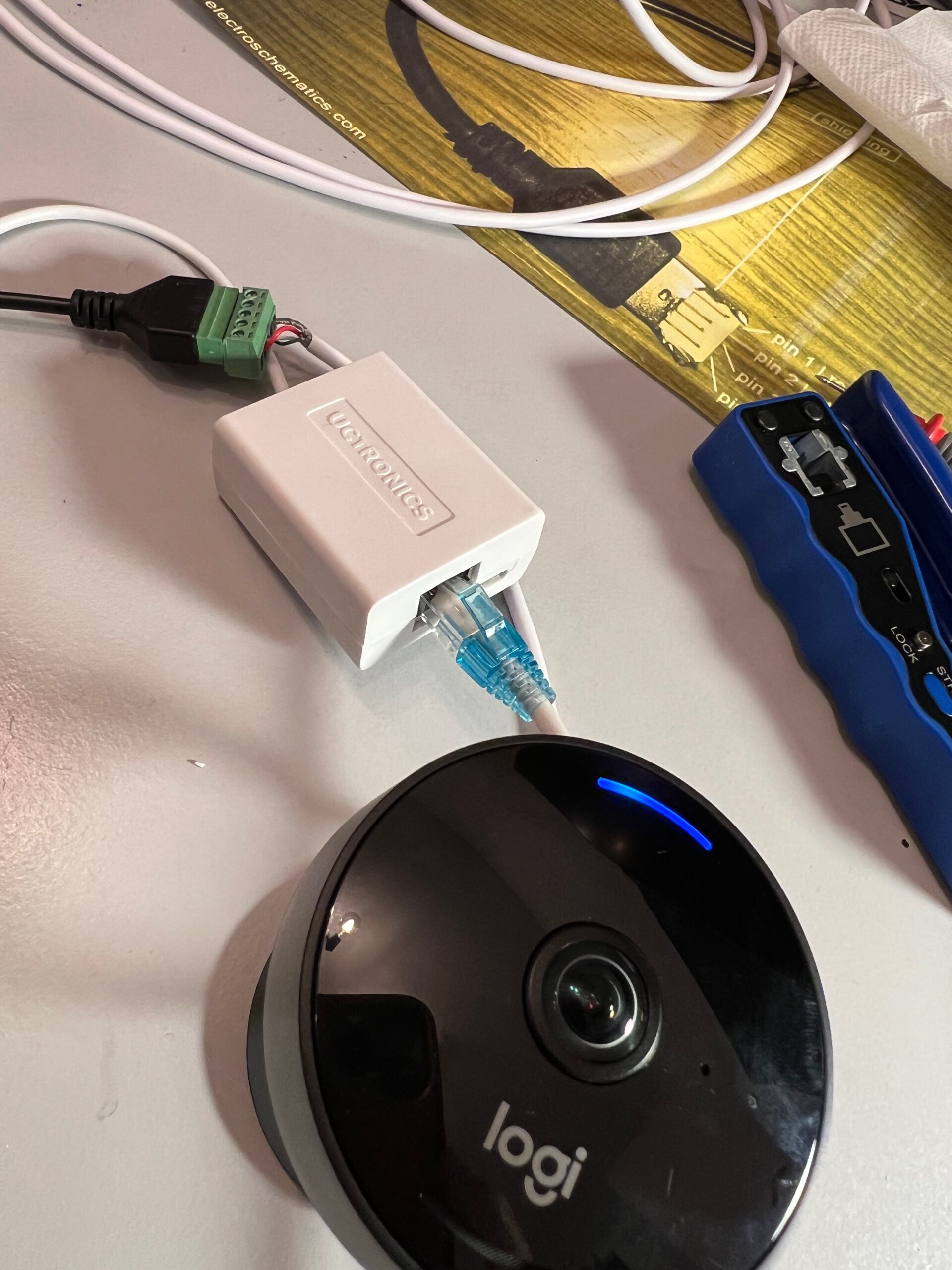
We are ready for the first test run! Please, double check the polarity of the wires. Reverse polarity could easily break the camera!
Connect the PoE Adapter to the micro USB female connector and then power it on via the ethernet cable. 🤞
Let’s leave the lab and go outdoors
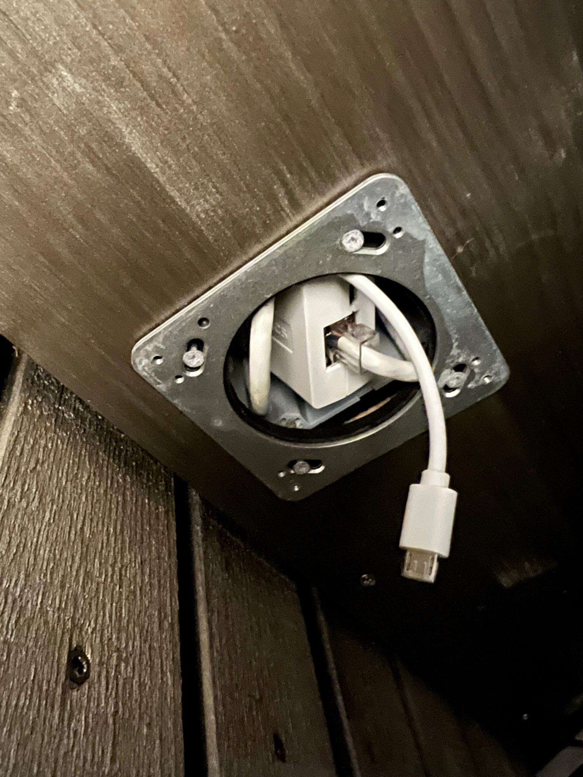
At first, we need to install an ethernet cable and crimp the plug. Then try to fit the Poe adapter into the EU box and connect it. After that, mount the camera and wrap the remaining cables into the lid of the blind cover. This allows us to mount it much easier in the final step.
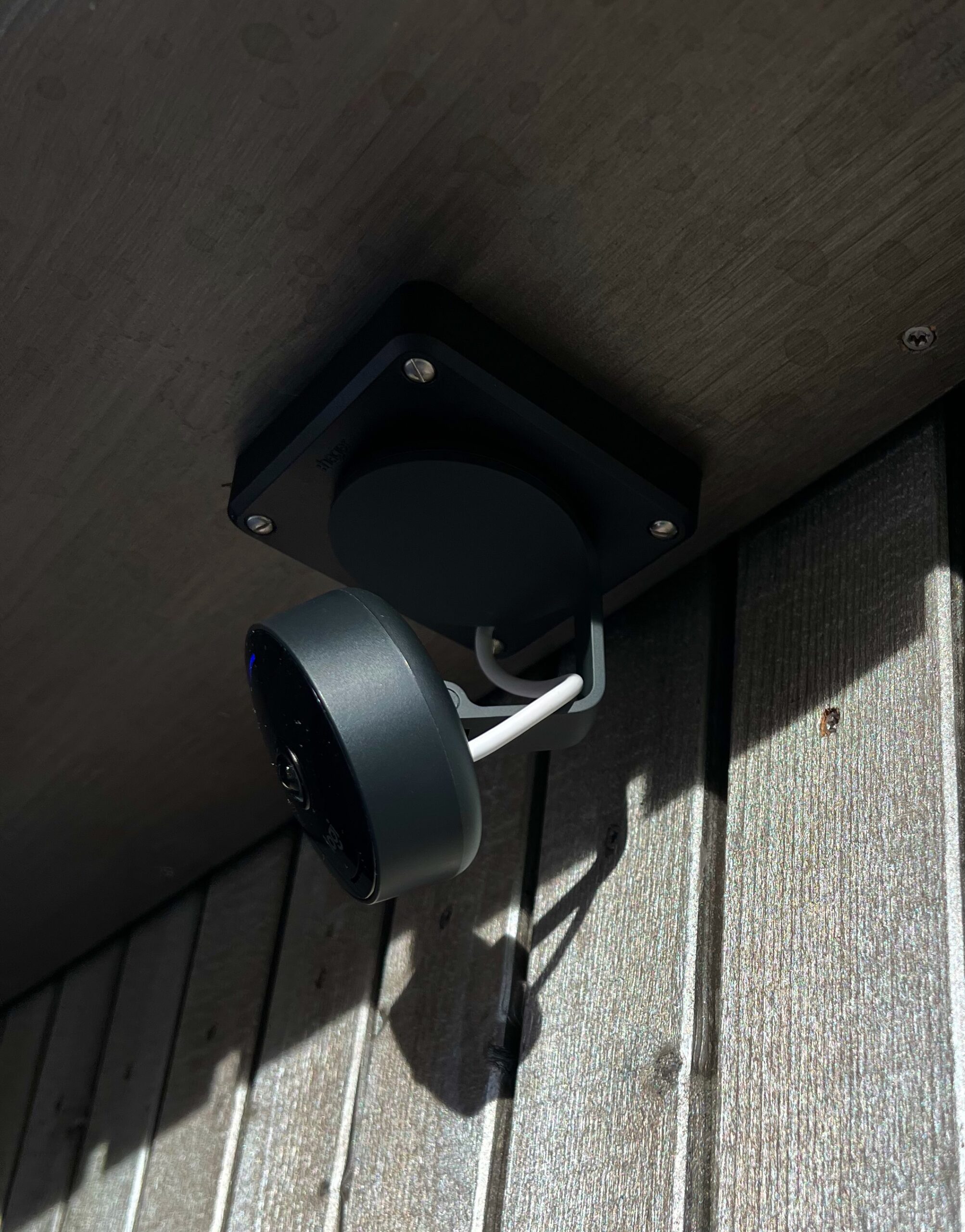
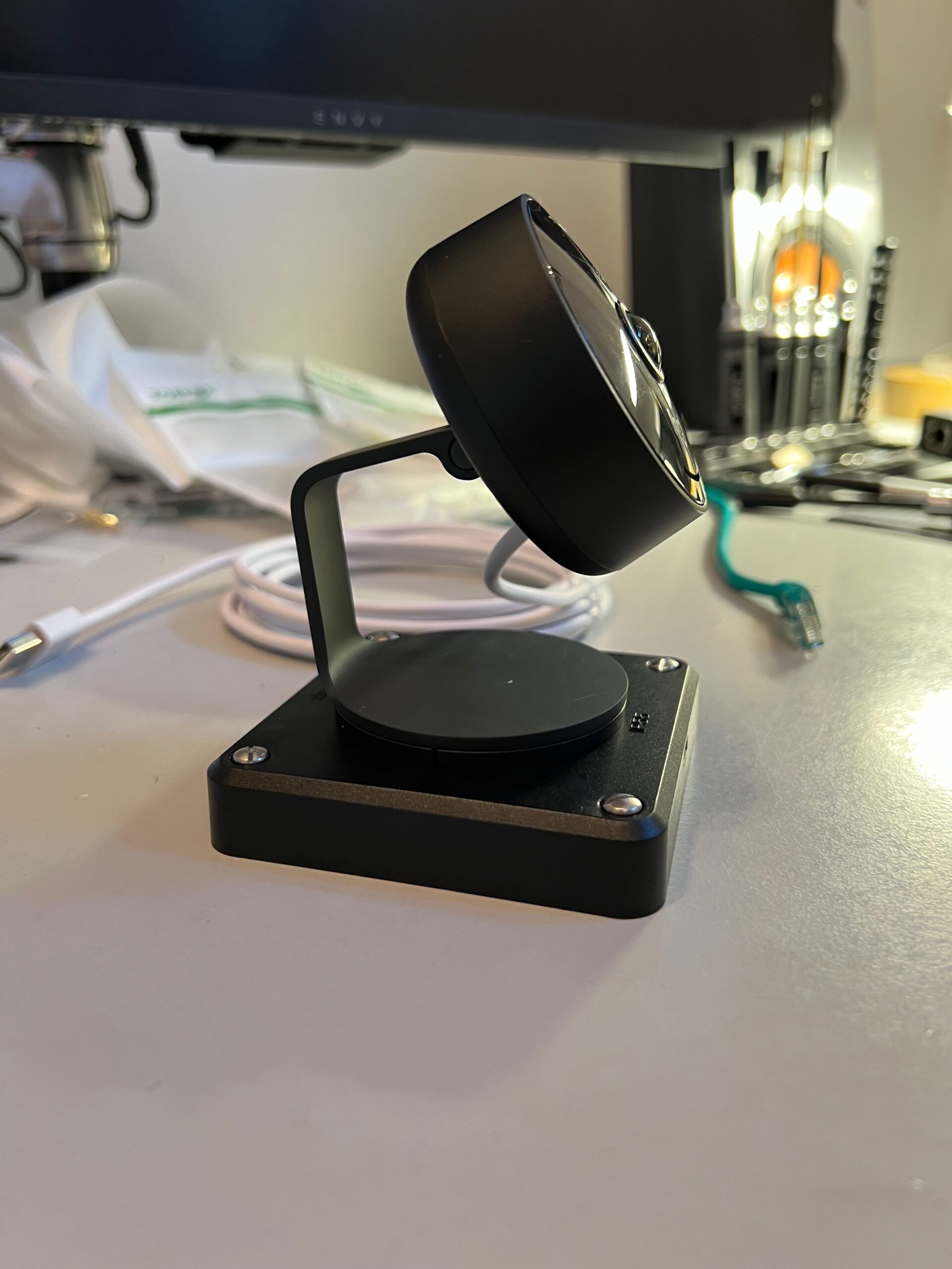
Finally, we can connect the PoE adapter to the camera and mount it on the ceiling. done!
I hope I was able to provide some guidance on how to power the Logitech Circle View Homekit enabled camera outdoors via PoE.
Hi there,
Are you experiencing any disconnect issues with this set up?
Using the stock power adapter causes the camera to go constantly offline multiple times a day.
Did you already test with another power adapter?
I don’t experience this with this setup also not during the winter months but I also have a lot of connection failures for my other homekit camera.
These issues are mostly related to wifi channels hops and similar on my environment (unifi APs). The homekit cams seem to be quite picky in terms of connectivity
I want to do this. I understand it all but one thing. What do you have as the source on the other end of the ethernet cable?
Hi Brandon
As source of power I got a Catalyst PoE+ switch but any PoE injector should do the trick.
Christian
This looks awesome—thank you so much for sharing! I keep wishing there was a schematic of what you created… because I find myself bouncing from picture to picture wondering if I understand everything you did. I like to start all projects with a schematic (one that includes everything).
Hej Scot, thanks for the feedback. I can look what I can do for the upcoming projects. 🙂
Try to have a close look on the pin mappings table and explanation I have added, the rest should be straight forward.