
How to build an Ambilight for every HDMI input source
This guide will then go one step further and enable the ambilight effect for all kind of HDMI input sources like PS3, XBOX, Chromecast etc.
We need to get the color information from an HDMI input signal. For this purpose, it’s necessary to transform the digital HDMI signal to an analog composite one with a converter. After this, we can grab the composite signal with an USB video grabber connected to the Raspberry Pi. Now we’re able to feed Hyperion with the color information by the video grabber.
Parts list
| AVR Receiver | It’s essential. Most TVs don’t offer an HDMI output |
| HDMI to Analog converter | Speaka Professional HDMI / Composite Converter. There are several others on the market, make sure that you got one with 1080p support. Check this guide for more details about the available chipsets |
| 2 port HDMI splitter | My AVR features two HDMI outputs. Otherwise make sure you’ll get one! |
| USB Video Grabber (Easycap) | |
| Composite cabel | Just a standard video cinch cabel |
| Active USB Hub | The Raspberry won’t be able to power most of the devices directly from it’s USB port. |
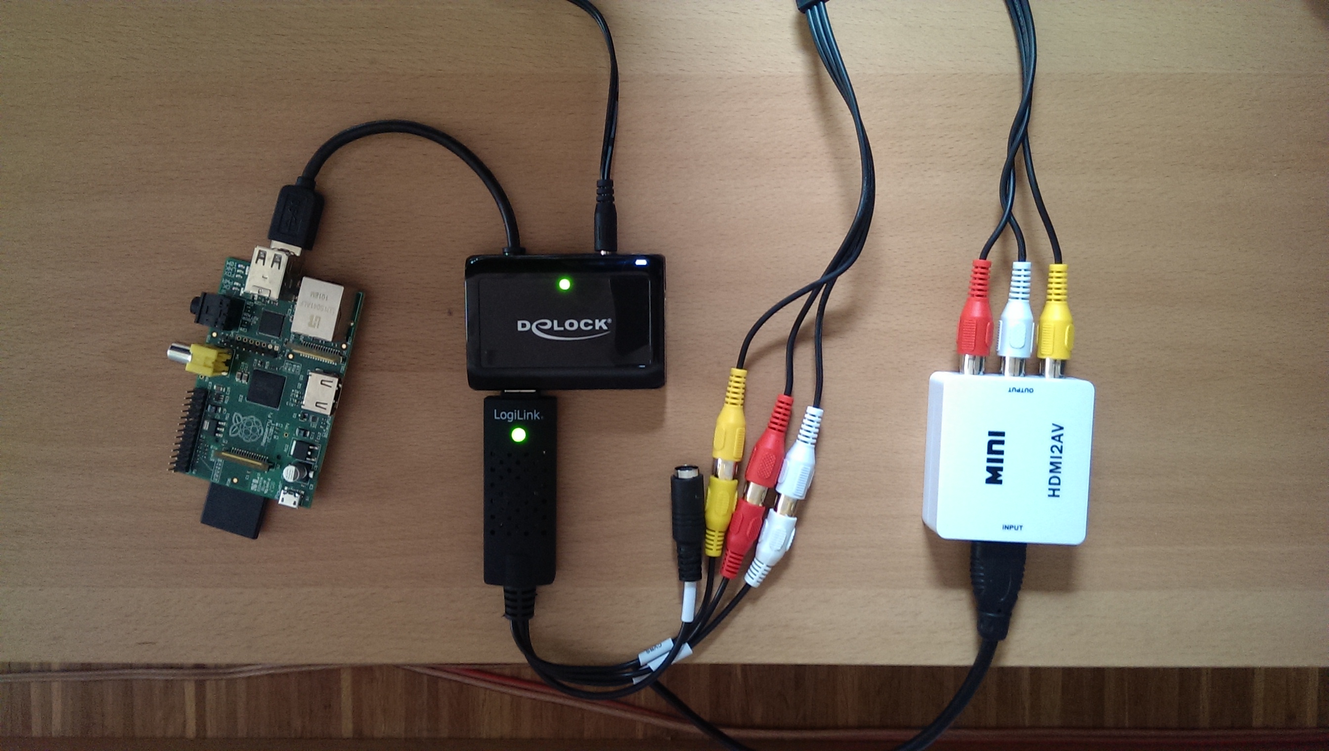
Let’s wire it up. Connect the HDMI output from your AVR or from your HDMI splitter to the HDMI / Composite converter input. Use the composite cabel for connecting the USB video grabber with the Composite converter analog output. Plug the USB video grabber into the active USB hub, connect the hub to the Raspberry Pi.
If you already have a running media center then you might already have an analog video output on this machine. In this case, connect the analog output to the grabber, directly. Another possibility would be to go for an DisplayPort to composite converter that connects to the USB grabber. For both solutions, make sure that your existing media center is capable of playing your media to both outputs, simultaneously otherwise you’ll need to go for a 2 port HDMI splitter (without AVR) and HDMI to composite converter.
Here’s my setup connected, ready for video capturing from any HDMI input.

1. USB Video Grabber setup
Connect the USB Video Grabber to the Raspberry and type
// List all connected USB devices
lsusb
// If you're lucky and got a supported STK1160 chipset device, it should list following id:
ID 05e1:0408 Syntek Semiconductor Co., Ltd STK1160 Video Capture Device
// If successfully loaded, your grabber's video input should be found under /dev.  For example: /dev/video0
ls /dev/video*
// Remember the output, we'll need it later
Unfortunately, my device with “ID 1b71:3002” features a Fushicai UTV007 chip, which is only initial supported with kernel 3.11. This forced me to compile the kernel module myself. If you got the same problem, here’s my precompiled module “usbtv.ko” for Raspbmc with kernel 3.10.36. Make sure you first load the modules “videobuf2-vmalloc” and “videobuf2-core”, than load the module with insmod usbtv.ko.
OpenElec (>=4.2.1) has the driver for Fushicai UTV007 already included, therefore it will work out of the box. Remember, to enable ssh you have to boot OpenElec with TV connected. After that, you won’t need the installed XBMC/KODI anymore. It seems like the current Raspbmc release has the driver not included. SSH to openelec and install hyperion:
curl -L --output install_hyperion.sh --get https://raw.githubusercontent.com/tvdzwan/hyperion/master/bin/install_hyperion.sh
sh ./install_hyperion.sh
Then copy your hyperion.config.json to the shared SMB “Configfiles” folder from your host system. The shared “Configfiles” folder is actually mapped to /storage/.config on the Rpi filesystem. After a Rpi reboot, Hyperion should autostart and load the config from /storage/.config/hyperion.config.json automatically, though.
Remember that you have to set the library path for OpenElec setups before you can execute any hyperion command:
cd /storage/hyperion/bin
Stop / Restart hyperion manually:
killall hyperiond
LD_LIBRARY_PATH=/storage/hyperion/bin /storage/hyperion/bin/hyperiond /storage/.config/hyperion.config.json
Take a screenshot from the grabber with following command. Remember to kill hyperiond before you can execute this command properly!
LD_LIBRARY_PATH=/storage/hyperion/bin /storage/hyperion/bin/hyperion-v4l2 /storage/.config/hyperion.config.json --screenshot
For further instructions, make sure to checkout the documentation.
2. Hyperion configuration
Hyperion already features capturing color information from a USB video grabber. Add following configuration to your hyperion.config.json file to enable it.
        /// Configuration for the embedded V4L2 grabber
        ///  * device          : V4L2 Device to use [default="/dev/video0"]
        ///  * input           : V4L2 input to use [default=0]
        ///  * standard        : Video standard (no-change/PAL/NTSC) [default="no-change"]
        ///  * width                : V4L2 width to set [default=-1]
        ///  * height               : V4L2 height to set [default=-1]
        ///  * frameDecimation      : Frame decimation factor [default=2]
        ///  * sizeDecimation       : Size decimation factor [default=8]
        ///  * priority             : Hyperion priority channel [default=800]
        ///  * mode                 : 3D mode to use 2D/3DSBS/3DTAB (note: no autodetection) [default="2D"]
        ///  * cropLeft             : Cropping from the left [default=0]
        ///  * cropRight            : Cropping from the right [default=0]
        ///  * cropTop              : Cropping from the top [default=0]
        ///  * cropBottom           : Cropping from the bottom [default=0]
        ///  * redSignalThreshold   : Signal threshold for the red channel between 0.0 and 1.0 [default=0.0]
        ///  * greenSignalThreshold : Signal threshold for the green channel between 0.0 and 1.0 [default=0.0]......
        ///  * blueSignalThreshold  : Signal threshold for the blue channel between 0.0 and 1.0 [default=0.0]
        "grabber-v4l2" :
        {
                "device" : "/dev/video0",
                "input" : 0,
                "standard" : "no-change",
                "width" : 1,
                "height" : 1,
                "frameDecimation" : 2,
                "sizeDecimation" : 4,
                "priority" : 800,
                "mode" : "2D",
                "cropLeft" : 10,
                "cropRight" : 8,
                "cropTop" : 12,
                "cropBottom" : 19,
                "redSignalThreshold" : 0.4,
                "greenSignalThreshold" : 0.2,
                "blueSignalThreshold" : 1.0
        },
To adjust the cropping for your setup, you have to change the values “cropLeft, cropRight, cropTop, cropBottom” and make sure “device” matches with your ls /dev/video* output!
// Stop hyperion
sudo initctl stop hyperion
// start any HDMI video source and make a screenshot from the grabber input. This will use the external v4l2 grabber
hyperion-v4l2 --crop-top 0 --crop-bottom 0 --crop-left 0 --crop-right 0 --size-decimator 4 --frame-decimator 2 --red-threshold 0.4 --green-threshold 0.2 --blue-threshold 1.0 --screenshot
Check the created screenshot.png, adjust the crop-* values till the grabbed input has no black borders left. Then put the calibrated values into your /etc/hyperion.config.json file.
Screenshot from my USB grabber input, I was able to get rid of the upper and lower borders by adjusting the cropTop and cropBottom values. I was able to get rid of the green lines after increasing “frameDecimation” to 8 but then a lot of frames were skipped and the LED’s were out of sync to the moving picture. So I set it back to 2.

If you only want to grab the signal from the v4l2 video grabber, make sure that you remove the “framegrabber” and xbmcVideoChecker sections.
// After you have checked the screenshots and configured your cropping values, start hyperion with the internal v4l2 grabber again
sudo initctl start hyperion
Let’s test some videos! If you don’t like the results, try to fine tune your setup with different SignalThresholds or try to adjust the hsv settings. Make sure to read this comprehensive guide about color transformation.
When you switch the HDMI source on your AVR to non HDMI sources, like for example audio only devices, the LED’s will light up in blue. Blue is the default color if no video source was detected for many AVRs. You can disable the LED’s in this situation by setting the blue-threshold value to 1.0.
3. Conclusion
Now you should be able to use your Ambilight for any HDMI input you have connected to your AVR. If you have any question, feel free to ask in the comments section. Enjoy your unleashed Ambilight!
Christian,
Thank you for taking the time to make this tutorial! It is very detailed and very much appreciated!
I apologize for digging up an old project but I’m having issues obtaining a screenshot. I have hyperion uploaded, already uploaded my configuration (as well as the grabber info) to the json config file but I can’t see to get it to grab a screenshot. Below is my putty command window (so you can see what I’m typing in, maybe I’m setting something up incorrectly):
https://postimg.cc/PC6ZHWwt
It appears to recognize the grabber I’m using (which I tested above), the PS4 video is coming through correctly on the splitter (as I can see it going back into the TV so I assume it’s also making it to the AVI2HDMI I’m using (which I have selected to 1080p to ensure it’s not trying to downconvert my signal):
https://www.amazon.com/GANA-Composite-Converter-Adapter-Supporting/dp/B01L8GG6PW/ref=sr_1_3?keywords=avi+to+hdmi&qid=1555655281&s=gateway&sr=8-3
Unfortunately, I’m not getting any screengrabs so I can’t really get much further in the process without it. I thought I’d post here and see if you had any suggestions.
Thanks again for all your help!
Hi Chris,
Would this be possible with DP 1.4, 3440x1440p, 21:9? Looking at upcoming Asus Rog Swift PG35VQ ultrawide.
All tips is much appreciated! 🙂
I have read the whole page, and I liked your solution, but I have a question too, What length of cable can this run over?
what operating system should i put on my sd card for this?
Dear christianmoser Team
Greetings for the day,
We feel glad to inform you that your website/blog titled (How to build an Ambilight for every HDMI input source and hyperlink”https://www.cmos.blog/techtalk//how-to-ambilight-for-every-hdmi-source/”) was covered by our teams on our website www.engineersgarage.com
The coverage can be locate at (Game Lovers- Got an Upgradation to your HDMI Input and hyperlink”https://www.engineersgarage.com/mygarage/game-lovers-got-upgradation-your-hdmi-input”). You may use the same link to share the story among your community/followers.
If you would like to submit more recently developed projects for review, you may contact us using the link (DIY Reviews, https://www.engineersgarage.com/submit/diy-reviews).
About EG:
EngineersGarage is a community of Electrical & Electronics Engineers which interacts with each other to learn and share technical knowledge. We publish high quality technical content which includes experiments, circuit design, tutorials and articles for the electronics fraternity. Our community comprises of active and loyal audience of design, research and product engineers from industries and hobbyists.
Key Statistics
1. EG currently serves 550k+ visitors every month.
2. Registered database of 300k+ engineers.
3. 1Million+ followers on Facebook.
Best Wishes
Team EG
[…] Original post from Christian Moser blog. […]
[…] Christian Moser […]
@christian, could you maybe re-create this whole DIY ambilight project for Ultra HD 4K (UHD = 2160p @ 60 fps)?
That is, replace the minimum componets need to instead of only support 1080p please put together a solution that does the same for when you have HDMI sources and a television that features Ultra HD 4K (UHD = 2160p @ 60 fps) output and input?
What I imagine is that you first need to replace the HDMI-splitter with a new HDMI-splitter (or HDMI matrix switch) that supports the new Ultra HD 4K (UHD = 2160p @ 60 fps) format, which requires HDMI 2.0 and HDCP 2.2 support, and then you need either replace the HDMI to Analog converter device with one that supports HDMI 2.0 and HDCP 2.2 for Ultra HD 4K (UHD = 2160p @ 60 fps) capure, or introdude a HDMI 4K to 1080p down-converter compoents.
An other possible solution could be you replace all the capture compoents and the Raspberry Pi with one of those cheaper Android media players which supports HDMI input and install Linux and capture software onto it, (several boxes like those are mentioned on cnx-software.com blog).
Hi thanks a lot for your request and suggestions. Unfortunately, I hardly have time for diy projects, currently but I’m looking forward to it!
Regards Chris
You could use these 2 devices together though they are exceptionally expensive, then daisy chain them in place between your IN source signal and OUT signal from the guide above. HDFury Integral(4k60 In) splitter, one Outpt to TV, other Output leads to HdFury Linker with downscaling setup to 1080p. This keeps within HDCP 2.2(well breaks it, but should work technically). HDCP killing good projects everywhere.
could anyone please post the parts and also let me know which raspberry pi model you have set it up for?
I’m having difficulty getting my colours calibrated correctly, my red is really dim, and my yellow is green. I’ve tried calibrating the colours in Hypercon following the Wiki but I’m struggling to get the colours correct, and simply can’t understand why my red is so dim.
Does anyone have a config file they can send me with their colour cal so I can test if they work on my setup?
Thanks,
I don’t know if anyone else has seen it, but somebody did this project and crammed it into a box. I plan on doing the same with the housing of an old 20-port Ethernet Switch enclosure and a PC PSU. I have drawn up a schematic, including all the parts/pieces needed to enclose the entire project (minus the enclosure and PSU). Thought it may prove useful for the public to share!
http://schematics.com/project/ambilight-box-32568/
Cool! Thanks for sharing.
I’m truly considering dumping the necessary funds into creating this fun project, however, I have a quick question or two regarding the system. The reason is I don’t have any ethernet connections in my room, only WiFi.
Does the Pi need to stay connected to the internet in order to fully function as an ambilight, or is the internet connection only necessary for preliminary configuration? If it needs internet for the life of the project, would it be possible to feed it data through a USB WiFi dongle?
No, once it’s fully setup you don’t need the connection anymore.
Thank you so much! One other thing, I plan on putting it all in one box and having all the devices powered by the same 5v power supply, is this going to be a problem? Should I be fusing each individual line for each device to prevent overdraw?
Please check my other ambilight guide where I explain how to calculate the required psu for the leds and rpi.
Chris,
Thanks for the great tutorial. All works great until I shut off the video source. I believe the MINI HDMI2AV produces a rainbow test pattern when the source goes off, even unplugging the HDMI2AV won’t stop the LEDs from lighting up in a rainbow pattern. Any thoughts?
Hi Can I use Hyperion with Beaglebone?
Hi,
Can I substitute the Pi B with a Pi zero or do you think I may have some kind of latency with the led?
Do you think that using a Pi 2 model B can bring any benefit to the project?
Thanks in advance 🙂
I’ve got it all working, but I have one problem:
I have the HDMI2AV BETTER version (white) and it’s set to NTSC.
My external decoder works with ambilight. But when I start my XBOX 360, the signal that comes out of the HDMI2AV is black, however on TV there is a signal.
When I switch the HDMI2AV to PAL, the LEDS light up and working like it should. But leaving HDMI2AV on PAL gives me a rainbow / no signal output when nothing is connected, so my leds always stay on.
I’ve tried several settings in hyperion config. Set it to NTSC, PAL, no-change but the rainbow keeps showing up in PAL or the xbox 360 doesn’t work with ambilight. What to do next? I don’t want to manually switch between NTSC and PAL on the hdmi2av everytime I play on the xbox.
Hi there!
I am looking around on ways to avoid having so many cables to do this and when I looked at the RPI2 I noticed he has 3.5mm jack with composite video. Would it be possible to connect the video cable straight from the HDMI2AV to the RPI2 like this?
I want to do 2 ambilight systems, one for my PC + Xbox One connected to my screen and since I have Win10 I can stream the games from the Xbox One to my PC and avoid having the HDMI splitter but this got me thinking… would it be feasible to do video capture of my desktop (and in this way also capture the video from the Xbox when I am playing) and stream it by USB or Ethernet cable (through my network) to the PI2 so that he can control the LEDS? And how?
My other system is for the living room that would be plugged to the Blu Ray that has 2 HDMI In and one out, from here it would get Netflix, my gf Xbox, Blu Ray movies and another PC if I plug it to the empty HDMI In. Here I could avoid the USB grabber if my first proposition works… but better yet it could avoid all the other cables IF the composite video out from the blu ray player can play video simultaneously with the HDMI out (I need to buy a cable to test this…)
Hi, as far as I know, the rpi2 doesn’t feature a composite video in but would be interested if you would find an arm based board that is capable of that.
For ambilight on your desktop you could try boblight for windows and point it to your hyperion rpi, which can be configured to listen for boblight commands over the network.
Hope this helps, regards Chris.
Hi.
Thank you for your guide.
My AVR have a composite video output.
Is it possible to use it instead of a hdmi to analogue converter ?
Regards,
Grimm
Hi, you’re welcome. In theory yes but most likely you won’t be able to use the composite out and the hdmi out of your avr at the same time. But it’s worth a try. Let me know your results, please.
Regards
I have no screen with composite input to test.
I should receive my usb video grabber tomorrow.
I will try this week-end to take a snapshot from the pi.
Hi! Do you have a step by step procedure on how to set up the software part?
thanks!
Hi Wilbert, check my other ambilight guide, please.
Hey,
What is that DeLock USB hub? I can’t seem to find it on Amazon or anywhere.
Thanks!
Chris
Just a USB 3.0 hub. Doesn’t really matter which one you choose, just make sure its active/powered.
Great info here! I was wondering if you might be able to help with a related issue. I’ve got everything hooked/wired up properly (with one issue). I can not get a proper signal/screenshot from my receiver (Onkyo RC260), but the entire set up works great if I just feed the Xbox One to the splitter. Obviously, I would like everything to have the effect, but the screenshots I take with my pi just look like a rainbow-colored image of the actual image on-screen (and this makes the entire LED system stay a soft white/red/pink color). But when I take a screenshot from the pi with just the Xbox hooked up, it looks just like it should. Playing Halo with the LED effect is great! I’ve tried swapping HDMI cables from all over the place, but still have the same issue. Any help would be great! Thank you.
Hello,
Did you find a solution to this problem as I have the same issue?
Thanks,
Hi there Chris.
I just dropped by to say thank you for this and your previous tutorial on non Philips Ambilight solutions. I`m planning a TV upgrade to something other than Philips TV, and because my other half loves Ambilight I wanted to keep that.
I will pop by once I`ve put something together.
Thanks again!!
Mat
You’re very welcome!
Hi Chris, thanks for the tutorial, works great, the only issue I am having is when the screen goes black the lights are still glowing for 5 seconds or so then turn off…any idea what could be causing this? Black levels too high perhaps?
[…] Christianmoser.me […]
Hi, first thanks for that awesome Tuto !
I have a slight issue. When I take a screenshot I get a lot of green lines on my image. Do you know what can be the issue ?
Thanks !
And it’s seems that it’s not hapenning to every frames. Sometimes I get one normal (without the green lines)
Hi Ludo, you’re very welcome.
My setup has the same issue, it shouldn’t have much input on the color grabbing. You can try reduce the lines by playing areound with sizeDecimation (8) and / or frameDecimation (2) in hyperion.config.json.
Regards Chris
Thanks for this tutorial!
Small question, my screenshot is pretty red and i can’t seem to get it to show in normal colors. Any ideas? I’ve tested around with the thresholds..
Thanks for the support.
You’re welcome. increasing the “redSignalThreshold” and restart hyperion should work. Did it change anything?
Hey there!
If i do not have a AVR in my system can i use a dual output HDMI splitter(such as http://www.amazon.com/gp/product/B00H9916WG/ref=gno_cart_title_0?ie=UTF8&psc=1&smid=A2BUXD0L1W5AKG) to get the same results with a single pi?
Is it possible to use the on board HDMI port on a pi2 for capture if i only want the pi for ambilight?
Hi John, yes, you can use a splitter in combination with a video grabber. You can’t use the rpi HDMI for grabbing because the digital hdmi signal can’t be easily decrypted.
wow I’m glad to fund this page! I’ve been looking for an Ambilight solution for my project to work with all my device no just Movies from HTPC other than arduino,teensy board solution!!
before going deep to this project and buy all I need I want make sure if can be done for me can you help?
first my Amilight project will be for a big fixed screen 108Inch with around 250Led
lucky I bought recently a AVR yamaha 2040 with 2 output HDMI simultanous 🙂
so if I understand your tutorials I wont need a spliter right? just a hdmi2AV ?
so can you conform
I can I use a raspberry pi to compute the ambilight form hyperion to the light strip and have my HTPC,PS4 to output video at the same time?
what is the lag? do I need to be limited for number of light before fps drop with raspberry or it’s unlimited?
what type of light strip it’s supported with this raspberry configuration? ws2801,2811,2812b…ec?
thank you
Chris
Hi Chris,
Yes, you won’t need a splitter and use the PS4 and the ambilight at the same time. I’d recommend WS2801, it’s cheap and you can connect it directly to the Rpi. I have no experience with so many LED, you’d need to try and tweak if it’s not working. My setup with 138 LEDs works very smooth.
Chris
Thanks Chris!!!
well I’m going with a different led after some reseach,I will have 140 led 36mm Square 12V Digital RGB LED Pixels – WS2801 they will put .9watt/ by pixels around the screen so i think i should be fine 😉
now I have another question:
I pre wired my home theater stuff into a cabinet witch is about 15ft from the the projector screen led strip and I would like to have the raspberry,usb graber…ect in there as well
I pre wired some 18 awg and 14awg electric wire that goes to the raspberry board later
so do you think 15ft long wire will be fine to run smooth into the led strip or do I need to have an USB cable of 15 ft that goes to the raspberry on back of the screen instead?
Hi Chris,
I’m curious about the final result with those interesting square LED, please share 🙂
I would definitely recommend the USB cable approach, since SPI is designed for short distance communication between integrated circuits.
regards
Hi Christian,
I like to know something before i order devices:
My AV receiver from Yamaha (A840) has an video (monitor) output. So i think I do not need a HDMI splitter and a HDMI2AV converter. I can connect the Video Grabber directly. Is it right or have i misunderstand something?
Thank You for your support
Hi, you should check if the AVR is able to output a signal through the HDMI & the monitor at the same time. Regarding the manual, this functionality was blocked for my AVR because of copyright reasons of HDMI material.. but if yours is capable of this, you won’t need a HDMI splitter and HDMI2AV converter.
If not, it looks like the 840 AVR got two HDMI out, so you would just need a HDMI2AV converter, no splitter.
Regards Chris
Hi Christian,
I have a problem with my splitter and av converter.When I toke scrrenshot form grabber I got blackscreen(TV007 Fushicai chipset).After that I checked my splitter and converter I couldnt find which has a problem. Because when I test them without connect to eachother they are working.
My Scenarios :
PS4 -> HDMI2AV -> TV ıts ok, working.
PS4 -> HDMI splitter -> out 1 TV1
-> out 2 TV2 both of them working,too.
PS4 -> HDMI splitter -> out 1 working
-> out 2 HDMI2AV -> TV2 not working.
PS4 -> HDMI splitter -> out 1 HDMI2AV -> TV2 not working.
-> out 2 TV1 working
Which one has a problem do you think ? Thanks for your helps.
My devices
http://imgur.com/kqvaA7X
http://imgur.com/DgQjwxN
Hi, is your hdmi2av converter able to downscale 1080p signals? Could you try to lower the resolution to 720×576 for the hdmi input device. Could be that the splitter forces the signal to 1080p, while the hdmi2av would set it to 720p.
Regards Chris
I think it is able to downscale 1080p signals. Because when I connect ps4 to hdmi2av directly to the TV’s AV input I can see the ps4 screen.
I think my hdmi2av is Fake 🙁
I have to buy new one. Thanks for your helps.
http://imgur.com/Hfyo9KS
I changed my hdmi2av .Now its ok , working perfect . Thanks
Hi, i’m having the same issue as you, where did you get your working HDMI2AV convertor from??
Hi Christian,
I’m having a problem that I can’t seem to figure out and I was hoping on having your insight. Everything seems to be working well but there is a slight lag between what is shown on the TV and the LED color. I would say there is a 1/2 second lag. I have played around with the smoothing settings but I do not think the problem is related to it after toying around with it.
Any ideas on how I can get rid of the lag? I have 173 LED’s for my setup. Is that too long?
Thank you for the help as always
Good morning.I managed to install and run my LED strip with Open Elec, but when trying to install video grabber (fushicai) LEDs do not follow the TV (set top box). I connected as follows: (RPI – TV); (Set top box – TV and grabber) and (grabber – RPI).
My Json setting was so.
…
“endOfJson” : “endOfJson”,
/// Configuration for the embedded V4L2 grabber
/// * device : V4L2 Device to use [default=”/dev/video0″]
/// * input : V4L2 input to use [default=0]
/// * standard : Video standard (no-change/PAL/NTSC) [default=”no-change”]
/// * width : V4L2 width to set [default=-1]
/// * height : V4L2 height to set [default=-1]
/// * frameDecimation : Frame decimation factor [default=2]
/// * sizeDecimation : Size decimation factor [default=8]
/// * priority : Hyperion priority channel [default=800]
/// * mode : 3D mode to use 2D/3DSBS/3DTAB (note: no autodetection) [default=”2D”]
/// * cropLeft : Cropping from the left [default=0]
/// * cropRight : Cropping from the right [default=0]
/// * cropTop : Cropping from the top [default=0]
/// * cropBottom : Cropping from the bottom [default=0]
/// * redSignalThreshold : Signal threshold for the red channel between 0.0 and 1.0 [default=0.0]
/// * greenSignalThreshold : SigSignal threshold for the blue channel between 0.0 and 1.0 [default=0.0]
“grabber-v4l2” :
{nal threshold for the green channel between 0.0 and 1.0 [default=0.0]
/// * blueSignalThreshold :
“device” : “/dev/video0”,
“input” : 0,
“standard” : “no-change”,
“width” : 640,
“height” : 480,
“frameDecimation” : 2,
“sizeDecimation” : 8,
“priority” : 1000,
“mode” : “2D”,
“cropLeft” : 26,
“cropRight” : 27,
“cropTop” :20,
“cropBottom” : 20,
“redSignalThreshold” : 0.1,
“greenSignalThreshold” : 0.1,
“blueSignalThreshold” : 0.1
},
Hi, are you able taking screenshots with the grabber?
yes, the screenshot is perfect but every time I turn on RPI the lights follow the screen KODI and not TV (Set Top Box)
ok, that’s good to hear. Then all you need to do, is to lower the “priority” setting of the v4l2 grabber. Default is 800, the lower the value, the more priority the grabber gets. Try lowering the priority until the grabber is chosen over the xbmcVideoChecker.
thanks, I’ll try it.
Sorry for my English, I do not speak English very well. I live in Brazil.
I use WinSCP to tranfereir files between windows and RPI. I deleted the file hyperion.config.json who was in the RPI, but the LED continued to work as before. This is normal?
What version of OpenElec you use, I’m using the latest version.
I will try your suggestion.
Sorry my bad writing.
Did I copied the file to the wrong place. The file is in the / storage / hyperion / config and in the / storage /. I can not find the configfiles folder.
for openelec you have to copy the config file to: /storage/.config/hyperion.config.json then stop and restart hyperion:
killall hyperiond
LD_LIBRARY_PATH=/storage/hyperion/bin /storage/hyperion/bin/hyperiond /storage/.config/hyperion.config.json
or
reboot
I’ll try when at home. thank you
Hello, I managed to make it work. The problem was that I was putting the .json file in the wrong folder. The correct folder is the folder / configfiles. Unfortunately for WinSCP I could not see this folder. I had to enter through windows explorer. Thank you for your help.
I just wanted to say thanks for writing this all up! I mostly have it all working but I’m running into an issue where the crop values are being ignored whenever I take a new screenshot.
Do you have any pointers on how to fix this?
Thank you!
Hi Steve, your welcome!
The parameters in the hyperion.config.json are not taken into account when you take a screenshot. Therefore, you have to add the crop values and all other arguments for the screenshot command to get the same resulto r what do you mean?
Regards Chris
I use the following totake a screenshot:
“LD_LIBRARY_PATH=/storage/hyperion/bin /storage/hyperion/bin/hyperion-v4l2 /storage/.config/hyperion.config.json –screenshot”
Which does not allow me to change the crop values.
But when I tried to take a screen shot using what you wrote in the later portion of your tutorial: “// Stop hyperion
sudo initctl stop hyperion
// start any HDMI video source and make a screenshot from the grabber input. This will use the external v4l2 grabber
hyperion-v4l2 –crop-top 0 –crop-bottom 0 –crop-left 0 –crop-right 0 –size-decimator 4 –frame-decimator 2 –red-threshold 0.4 –green-threshold 0.2 –blue-threshold 1.0 –screenshot”
I get the following error: ” hyperion-v4l2: not found”.
What is the proper command where I can add in the crop values and other arguments?
Just as I sent my last reply, I had a lightbulb moment! I think I have everything set up and will be doing a first test on the LED’s!
Hi Chris,
I finally have everything hooked up but I’m running into some problems.
1) for some reason, only a quarter of my LEDs are on. and it seems like its only the center 20 or so. And the ones that are on are only Red Green and Blue. Any ideas on why this is happening? I’ve already checked the screen shot and it looks good to me.
2) As mentioned in 1, only part of the LED lights are on and it seems to be the center that are on. I sized my power supply correctly (5v, 10A) and should work with my 153 LEDs.
Thanks for all the help!
Hey Christian, great guide!
I’ve managed to create a similar setup of my own. But I have some problems. When I capture a screenshot I get a lot of interference.
http://imgur.com/LFxTxq5
I captured my computer when I only had a chrome window up and a terminal in the bottom right corner. As you can see its a mess of odd colors, which in turn results in flickering of the leds and incorrect colors.
Do you have any idea what may cause this?
My setup is like this:
AVR -> HDMI splitter -> 1 to Projector, 1 to a HDMI to AV converter similar to yours. (http://www.deltaco.eu/en/product/(AV-HDMI1)/Deltaco-AV-HDMI1—Video-converter—HDMI—black/). Converter -> logilink grabber (STK1160 chipset) -> raspberry running rasbian with hyperion.
Could it be the grabber? Maybe faulty drivers. I will try to do some debug, checking output in each step.
You could try a grabber with TV007 (Fushicai) chipset.
Yeah, I think I’ll find another grabber with TV007.
When I checked the composite output after the converter the image was ok, although it had a bit of interference. Maybe I’ll try to find another converter as well.
Hi.
Great guide, very easy to implement.
Only issue I’m having is:
After setting all the cropping using command line:
“LD_LIBRARY_PATH=/storage/hyperion/bin /storage/hyperion/bin/hyperion-v4l2 –crop-top 0 –crop-bottom 0 –crop-left 0 –crop-right 0 –size-decimator 4 –frame-decimator 2 –red-threshold 0.4 –green-threshold 0.2 –blue-threshold 1.0 –screenshot”
and saving to values to /storage/.config/hyperion.config.json I’m trying to take a screenshot using:
“LD_LIBRARY_PATH=/storage/hyperion/bin /storage/hyperion/bin/hyperion-v4l2 /storage/.config/hyperion.config.json –screenshot”
but apparently the values are being ignored…
Any help would be appreciated.
Thanks
Hi
If Im ging to follow all your steps in this and in your First tutorial Can i still use xbmc with the ambilight? So Can i switch the hdmi input between the xbmc Mediacenter and for example my ps3 or an other input?
If you use two rpi, one just for capturing the hdmi signal and one just for the mediacenter then you don’t need to configure hyperion for xbmc as shown in my first tutorial. Just switch the hdmi input and you’re fine.
Hi,
I have a powered HDMI splitter (should be called a duplicater), but when it is connected to the HDMI to AV converter which in turn is connected to the grabber, itself connected to the Raspberry Pi, the TV signal is downscaled to 480 (from 1080p, 720p or whatever).
When I disconnect the converter or any piece of the chain, the signal to the TV dinamically reverts back to the original resolution.
I tested plugging the two outputs from the splitter to the TV, and I get two 1080p signals for instance (switching between HDMI1 and HDMI2 on TV). Again, if I plug the splitter output back to the chain that finishes as 480 AV signal, the HDMI that goes to TV is downscaled…
I understand the problem comes from the HDMI to AV converter. Can you confirm that the Speaka you have bought lets you have 1080p to the TV while enjoying the leds ?
I saw that the one you bought costs more than 50€. Mine was the cheapest, 12€. I don’t mine paying more to get a correct one, but 50€ seems too much…
Thanks
Hi Philippe,
There are at least three different HDMI splitters with different chipsets and capabilities. I have a proper 1080p signal on my setup. Please, check this really good guide about the chipsets, it’s worth to invest for the better hardware: http://m.aliexpress.com/item-desc/32248986965.html
Hi Christian,
thanks for the post 🙂
2 questions though:
1) When I have this setup configured, what about the HDMI output of the Raspberry? I mean when I watch movies coming from the raspberry pi storage? Where does the hdmi out go?…When I put it in the hdmi in of the hdmi splitter, I would have a loop, don’t I?
2) What about the TV signal? Does this setup cover the TV signal as well?
BR
Hi Marcus.
1) Rpi HDMI out to HDMI splitter in, splitter out_1 to TV, splitter out_2 to HDMI2AV.
2) If you use the built-in decoder of the TV then it won’t be able to grab the signal. For that purpose, you’ll need an external decoder and connect it as shown in 1).
Regards Christian